Blog
Automation and Instrumentation in Industry
Automation and Instrumentation in Industry: A Comprehensive Guide
In the dynamic landscape of modern industry, efficiency, safety, and precision are paramount. Achieving these crucial objectives relies heavily on two interconnected disciplines: automation and instrumentation. From manufacturing plants to the intricate operations of oil and gas facilities, these technologies form the backbone of contemporary industrial processes, enabling seamless control, optimisation, and rapid response to changing conditions.
This guide delves into the fundamental aspects of industrial automation and instrumentation, exploring their core principles, specific applications, the transformative impact of the Industrial Internet of Things (IIoT), and the critical role of Safety Instrumented Systems (SIS). By understanding these concepts, you’ll gain valuable insight into how industries worldwide are achieving unprecedented levels of productivity and reliability.
Industrial Automation Basics
Industrial automation refers to the use of control systems, such as computers, robotics, and other information technologies, to handle different processes and machinery in an industry to replace human intervention. The primary goal is to enhance productivity, improve quality, reduce costs, and increase safety in hazardous environments. This evolution from manual operations to automated systems has been a continuous journey, significantly shaping the industrial landscape since the first industrial revolution.
Evolution of Industrial Automation
The journey of automation started with mechanical aids, evolved through relay-based systems, and rapidly progressed with the advent of digital electronics, microprocessors, and software systems. The key milestones include:
- First Industrial Revolution: Mechanisation using steam power
- Second Industrial Revolution: Mass production with electrical energy
- Third Industrial Revolution: Digital computing and programmable control
- Fourth Industrial Revolution (Industry 4.0): Smart systems, AI, and IIoT integration
The Driving Force Behind Automation
Historically, industrial processes relied heavily on manual labour, which was often slow, prone to human error, and inconsistent. The advent of automation addressed these limitations by introducing precision, speed, and repeatability. Today, the benefits of industrial automation are multifaceted:
- Increased Productivity: Automated systems can operate continuously, 24/7, without fatigue, leading to higher output rates compared to manual processes.
- Improved Quality and Consistency: Machines perform tasks with a high degree of accuracy and repeatability, minimising defects and ensuring uniform product quality.
- Reduced Operational Costs: While initial investment can be significant, automation reduces labour costs, waste, and energy consumption in the long run.
- Enhanced Safety: By automating dangerous or repetitive tasks, industries can remove human workers from hazardous environments, significantly reducing workplace accidents.
- Optimised Resource Utilisation: Automation systems can precisely control the use of raw materials and energy, leading to less waste and greater efficiency.
- Better Data Collection and Analysis: Automated systems generate vast amounts of operational data, which can be analysed to identify trends, predict failures, and improve processes.
Core Components of an Automation System
A typical industrial automation system comprises several interconnected elements working in harmony:
- Sensors: These devices detect and measure physical quantities (e.g., temperature, pressure, flow, level, position) and convert them into electrical signals. Sensors provide the crucial input data that the control system needs to understand the current state of a process. Examples include thermocouples, pressure transducers, proximity sensors, and encoders.
- Actuators: These are devices that receive signals from the control system and perform a physical action to control a process. They convert electrical, hydraulic, or pneumatic energy into mechanical motion. Common actuators include control valves, motors (AC/DC, servo, stepper), pumps, and robotic arms.
- Controllers: The “brains” of the automation system, controllers process the input signals from sensors and generate output signals to actuators.
- Programmable Logic Controllers (PLCs): Widely used in discrete manufacturing and process control, PLCs are rugged, industrial computers designed to automate specific processes. They execute logic-based programs to control machinery.
- Distributed Control Systems (DCS): More complex than PLCs, DCSs are typically used in large-scale process industries (like oil refineries, chemical plants, power stations) where highly integrated control of multiple, geographically dispersed processes is required. They offer advanced control strategies, extensive data historisation, and system-wide visibility.
- Industrial PCs (IPCs) and Single-Board Computers (SBCs): Used for more complex automation tasks requiring higher computing power, data processing, and integration with IT systems.
- Human-Machine Interfaces (HMIs): These are graphical user interfaces that allow operators to monitor and control the automated processes. HMIs display real-time data, alarms, trends, and enable operators to adjust setpoints or initiate commands. They can range from simple push-button panels to sophisticated touchscreens and computer workstations.
- Communication Networks: These facilitate the exchange of data between sensors, actuators, controllers, and HMIs. Industrial communication protocols (e.g., Modbus, Profibus, EtherNet/IP, OPC UA) are designed for robust and reliable operation in industrial environments.
Benefits of Automation
- Increased Productivity: Systems work 24/7 without fatigue.
- Consistent Quality: Reduces errors caused by manual operations.
- Operational Safety: Removes workers from hazardous environments.
- Data Acquisition: Real-time insights improve decision-making.
Types of Automation
Automation can be broadly categorised into:
- Fixed Automation: Used for high-volume production of a single product. The equipment is designed to perform specific operations with little or no variation, offering high production rates but low flexibility (e.g., assembly lines for mass production).
- Programmable Automation: The sequence of operations can be changed by modifying the control program. Suitable for batch production where product variety is limited, but volumes are moderate (e.g., CNC machines, industrial robots).
- Flexible Automation: An extension of programmable automation, allowing for rapid and automatic changes in product design. It’s ideal for medium-volume, medium-variety production, offering high flexibility and high production rates (e.g., flexible manufacturing systems).
- Integrated Automation: A holistic approach where all processes, from design to manufacturing to business functions, are integrated and controlled by computer systems. This includes Computer-Aided Design (CAD), Computer-Aided Manufacturing (CAM), and Enterprise Resource Planning (ERP) systems.
Control Loops: Open-Loop vs. Closed-Loop
A fundamental concept in automation is the control loop:
- Open-Loop Control: The control action is independent of the output. The system simply executes a pre-programmed sequence without feedback (e.g., a simple timer-based sprinkler system). While simple, it’s not self-correcting.
- Closed-Loop Control (Feedback Control): The control action depends on the system’s output. Sensors measure the output, and this feedback is compared to a desired setpoint. Any deviation (error) triggers the controller to adjust the actuator to bring the output back to the setpoint (e.g., a thermostat controlling room temperature). This provides accuracy and self-correction.
Industrial automation is continually evolving, driven by advancements in artificial intelligence, machine learning, and connectivity. These developments are paving the way for more intelligent, autonomous, and interconnected industrial operations.
Instrumentation in Manufacturing and Oil & Gas
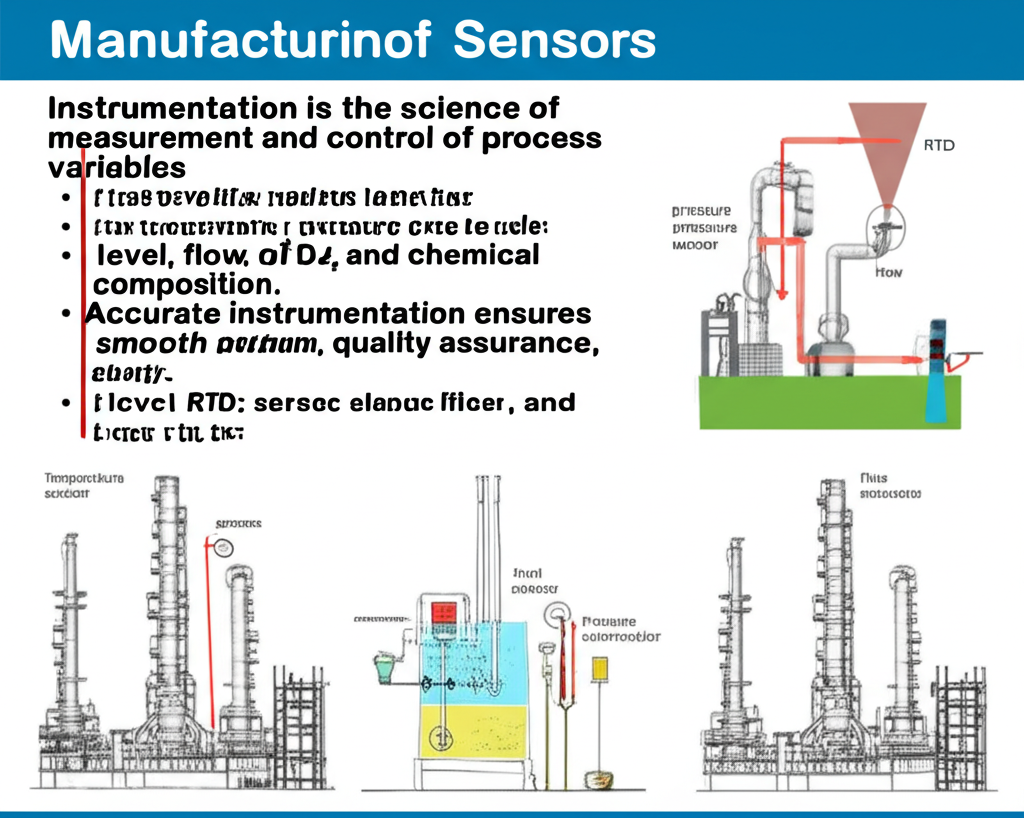
Instrumentation is the science and technology of measurement and control. In an industrial context, it involves the design, development, and use of instruments to measure, monitor, and control physical quantities within a process. These measurements are the eyes and ears of an automation system, providing critical data that enables effective process management and decision-making. Without accurate and reliable instrumentation, automation systems would be operating blindly, unable to maintain desired conditions or respond to anomalies.
The Indispensable Role of Instrumentation
Instrumentation is essential for:
- Process Monitoring: Providing real-time data on process variables, allowing operators to understand current conditions.
- Quality Control: Ensuring products meet specifications by accurately measuring parameters like temperature, pH, or concentration.
- Safety: Detecting abnormal conditions (e.g., high pressure, gas leaks) that could lead to dangerous situations, triggering alarms or safety shutdowns.
- Optimisation: Enabling fine-tuning of processes to maximise efficiency, reduce waste, and minimise energy consumption.
- Compliance: Meeting regulatory requirements for emissions, product quality, and safety standards.
Role of Instrumentation in Manufacturing
In a manufacturing setting, instrumentation:
- Monitors Critical Parameters: Ensures materials are processed under precise conditions.
- Supports Process Control Systems: Integrates with PLCs and DCS (Distributed Control Systems) to regulate machines.
- Improves Product Quality: Enables precision manufacturing through closed-loop control.
Instrumentation in the Oil & Gas Industry
The oil & gas sector is highly dependent on instrumentation due to:
- Explosive Environments: Instruments must be explosion-proof (Ex d/Ex ia rated).
- Harsh Conditions: Sensors need to withstand pressure, temperature, and corrosion.
- Pipeline Monitoring: Flowmeters and pressure sensors track oil or gas flow rates to prevent leaks and ensure compliance.
Common Industrial Instruments
| Instrument Type | Parameter Measured | Application Example |
|---|---|---|
| Thermocouples/RTDs | Temperature | Heat exchangers, furnaces |
| Pressure Transmitters | Pressure | Compressors, vessels |
| Level Sensors | Liquid Level | Storage tanks |
| Flow Meters | Flow Rate | Pipelines, fuel lines |
| pH/Conductivity Meters | Chemical Composition | Water treatment, chemical plants |
Common Industrial Measurements and Instruments
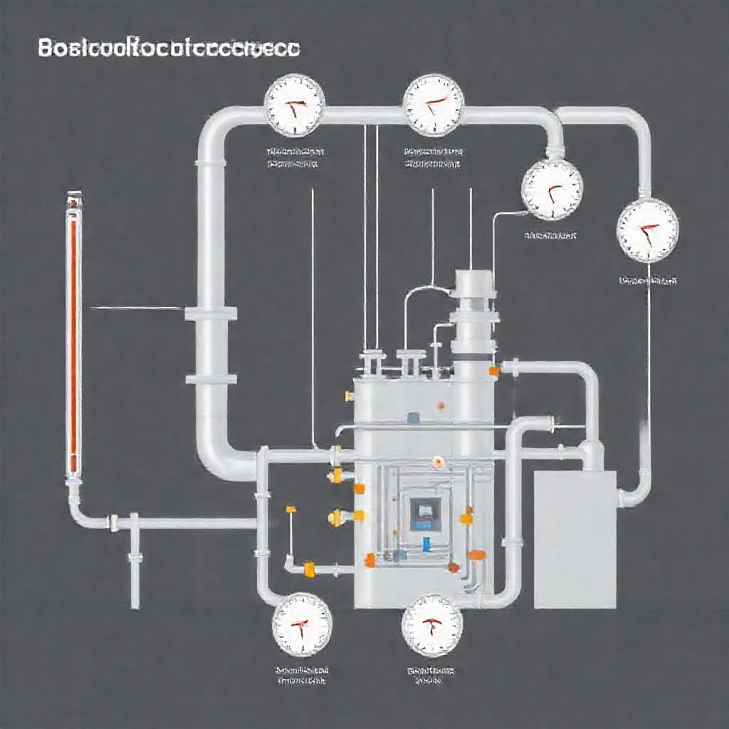
The four most commonly measured process variables in industrial settings are temperature, pressure, flow, and level. Each requires specific types of instruments:
- Temperature Measurement:
- Thermocouples: Based on the Seebeck effect, where a voltage is produced when two dissimilar metals are joined at two points and these points are at different temperatures. They are robust, wide-ranging, and commonly used in high-temperature applications.
- Resistance Temperature Detectors (RTDs): Utilise the principle that the electrical resistance of a metal changes with temperature. Platinum RTDs (Pt100) are very accurate and stable, ideal for precise measurements.
- Thermistors: Semiconductors whose resistance changes significantly with temperature, offering high sensitivity but a more limited temperature range.
- Infrared Thermometers: Non-contact devices that measure temperature by detecting the infrared radiation emitted by an object, useful for moving targets or hazardous surfaces.
- Pressure Measurement:
- Pressure Transmitters: Convert pressure into an electrical signal (e.g., 4-20 mA or digital signal). They often use diaphragms that deform under pressure, and this deformation is converted into an electrical signal via strain gauges or capacitive sensors.
- Manometers: Basic instruments that measure pressure using a column of liquid.
- Bourdon Tubes: A coiled or C-shaped tube that tends to straighten under internal pressure, used in mechanical pressure gauges.
- Diaphragm Seals: Used to protect pressure instruments from corrosive, viscous, or very hot process fluids, by isolating the instrument with a flexible diaphragm and a fill fluid.
- Flow Measurement:
- Orifice Plates, Venturi Meters, and Nozzles: These are differential pressure flow meters that create a pressure drop across a restriction, with the flow rate calculated from the pressure differential.
- Magnetic Flow Meters (Magmeters): Ideal for conductive liquids, these meters operate on Faraday’s law of electromagnetic induction, measuring the voltage induced by the fluid moving through a magnetic field.
- Coriolis Flow Meters: Measure mass flow directly, regardless of fluid density or viscosity, by measuring the inertial forces caused by fluid flowing through vibrating tubes. Highly accurate and versatile.
- Ultrasonic Flow Meters: Use sound waves to measure flow velocity, suitable for liquids and gases, and can be clamp-on (non-invasive).
- Turbine Flow Meters: Measure flow by the rotational speed of a turbine rotor placed in the flow path.
- Level Measurement:
- Differential Pressure Level Transmitters: Measure the hydrostatic pressure exerted by the liquid column to determine level.
- Ultrasonic Level Transmitters: Emit sound waves that bounce off the liquid surface; the time taken for the echo to return indicates the level.
- Radar Level Transmitters: Similar to ultrasonic but use microwave pulses, effective in challenging environments (e.g., vapours, varying temperatures).
- Float Switches: Simple mechanical devices that detect a specific liquid level using a buoyant float.
- Capacitance Level Transmitters: Measure changes in capacitance between a probe and the tank wall as the liquid level changes.
Instrumentation in Specific Industries
Manufacturing: In discrete manufacturing (e.g., automotive, electronics), instrumentation ensures precise positioning, temperature control in ovens, pressure regulation in pneumatic systems, and quality control through vision systems. In process manufacturing (e.g., food and beverage, pharmaceuticals), instruments monitor and control mixing ratios, fermentation temperatures, pH levels, and flow rates to ensure product consistency and safety. Calibration of instruments is crucial to maintain accuracy, and regular maintenance ensures reliability and longevity.
Oil & Gas: The oil and gas industry presents some of the most challenging environments for instrumentation due to extreme pressures, temperatures, corrosive fluids, and hazardous atmospheres.
- Upstream (Exploration & Production): Instruments measure reservoir pressure, flow rates from wells, gas-oil-water ratios, and drilling parameters. Subsea instrumentation must withstand immense pressures and operate reliably for long periods.
- Midstream (Transportation): Pipelines rely on instrumentation for pressure monitoring to detect leaks, flow measurement for custody transfer, and temperature sensing for pipeline integrity. Compressor stations and pumping stations are heavily automated and instrumented.
- Downstream (Refining & Petrochemicals): Refineries are highly complex chemical plants where instrumentation is critical for controlling distillation columns, reactors, heat exchangers, and storage tanks. Precise temperature, pressure, flow, and level control are vital for efficiency, product quality, and safety in handling flammable and toxic substances.
- Hazardous Area Classification: Instruments used in oil and gas must comply with strict regulations for hazardous area classification (e.g., ATEX, IECEx) to prevent ignition of flammable gases or dusts. This often requires intrinsically safe, flameproof, or purged enclosures.
The continued advancement in sensor technology, including miniaturisation and integration with communication capabilities, is revolutionising how instrumentation contributes to operational excellence and safety across all industries.
Industrial Internet of Things (IIoT) and Smart Instrumentation
The Industrial Internet of Things (IIoT) represents the convergence of information technology (IT) and operational technology (OT), extending the concept of the Internet of Things (IoT) to industrial applications. It involves connecting industrial assets, sensors, and machines to the internet, enabling them to collect, exchange, and analyse vast amounts of data. This paradigm shift is transforming industries by creating highly integrated, intelligent, and responsive operational environments.
The IIoT Ecosystem
At its core, the IIoT ecosystem comprises:
- Connected Devices (Things): These are the industrial assets, equipment, and, crucially, smart instruments equipped with sensors and communication capabilities.
- Connectivity: Networks (wired or wireless, e.g., Wi-Fi, Ethernet, 5G, LoRaWAN) that enable data transmission from the devices to the cloud or edge computing platforms.
- Data Collection and Processing: Gateways and edge devices that collect raw data from devices, filter, aggregate, and pre-process it before sending it further.
- Cloud Computing/Data Centres: Centralised platforms for storing, processing, and analysing large datasets using advanced analytics, machine learning, and artificial intelligence.
- Analytics and Applications: Software applications that interpret the processed data to generate actionable insights, predictive models, and visualisations for operators and management.
- User Interfaces: Dashboards and HMIs that present these insights to human users, enabling informed decision-making and control.
The Rise of Smart Instrumentation
Traditional instruments primarily focused on a single measurement and output. Smart instruments, a cornerstone of the IIoT, go beyond simple measurement. They incorporate microprocessors, embedded software, and communication capabilities, enabling:
- Self-Diagnostics: Smart instruments can monitor their own health and performance, detecting calibration drifts, sensor failures, or other anomalies and often communicating these issues proactively.
- Wireless Communication: Many smart instruments are now wireless (e.g., using WirelessHART, ISA100.11a), reducing installation costs, increasing flexibility, and enabling monitoring in remote or hard-to-reach locations.
- Multi-Variable Sensing: A single smart instrument can measure multiple process variables simultaneously (e.g., a smart flow meter might also measure temperature and pressure).
- Remote Configuration and Calibration: Instruments can be configured, calibrated, and troubleshot remotely, reducing the need for on-site visits.
- Enhanced Data Capabilities: They can store historical data, perform local calculations, and communicate richer diagnostic information beyond just the primary process variable.
Transformative Benefits of IIoT and Smart Instrumentation
The integration of IIoT and smart instrumentation offers profound advantages for industrial operations:
- Predictive Maintenance: By continuously monitoring equipment health and performance data (vibration, temperature, current draw), IIoT systems can predict potential equipment failures before they occur. This shifts maintenance from reactive (breakdown repairs) or preventative (scheduled, time-based) to predictive, minimising downtime, reducing maintenance costs, and extending asset lifespan.
- Remote Monitoring and Control: Operators can monitor and control processes from anywhere, enhancing operational flexibility and reducing the need for personnel in hazardous areas. This is particularly beneficial for geographically dispersed assets like pipelines or remote oil wells.
- Operational Optimisation: Real-time data from IIoT-enabled systems provides unparalleled insight into process performance. Advanced analytics can identify inefficiencies, optimise energy consumption, improve resource allocation, and fine-tune process parameters for maximum output and quality.
- Data-Driven Decision Making: The abundance of data, combined with powerful analytics tools, empowers management and operators to make more informed and strategic decisions, moving away from intuition-based approaches.
- Enhanced Safety: By continuously monitoring conditions and identifying anomalies, IIoT systems can provide early warnings of potential safety hazards, allowing for proactive interventions and reducing the risk of incidents. This can include monitoring gas leaks, equipment stress, or deviation from safe operating limits.
- Supply Chain Optimisation: IIoT can track assets, inventory levels, and logistics in real-time, leading to more efficient supply chain management and reduced lead times.
Challenges and Considerations
Despite the significant benefits, implementing IIoT and smart instrumentation comes with challenges:
- Cybersecurity: Connecting operational technology to the internet opens up new vulnerabilities. Robust cybersecurity measures are paramount to protect critical infrastructure from cyber threats.
- Data Integration and Interoperability: Integrating data from disparate legacy systems and various communication protocols can be complex.
- Scalability: Managing and processing the vast amounts of data generated by IIoT devices requires scalable infrastructure and sophisticated data management strategies.
- Skill Gap: A shortage of professionals with expertise in both IT and OT, as well as data science and analytics, can hinder adoption.
- Initial Investment: The capital expenditure for IIoT infrastructure and smart instruments can be substantial, requiring a clear return on investment (ROI) justification.
The IIoT and smart instrumentation are not merely technological upgrades; they represent a fundamental shift in how industries operate, paving the way for truly smart factories, digital oilfields, and interconnected enterprises that are more agile, efficient, and resilient.
Safety Instrumented Systems (SIS)
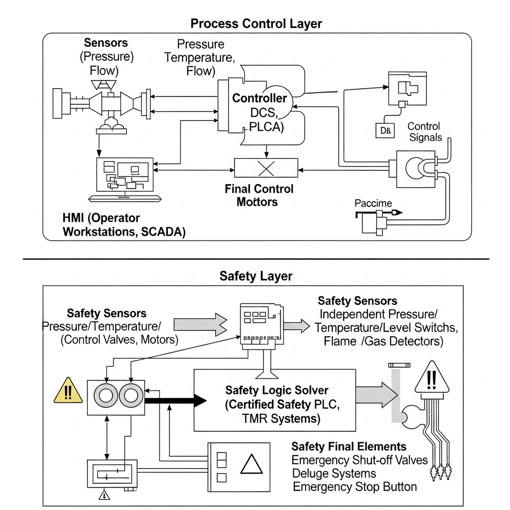
In industrial environments, particularly in process industries dealing with hazardous materials or extreme conditions, the risk of accidents is ever-present. While basic process control systems (BPCS) are designed to keep a process operating efficiently within its normal operating limits, they are not primarily intended to mitigate abnormal, hazardous situations. This is where Safety Instrumented Systems (SIS) come into play. A SIS is a dedicated, independent, and highly reliable system designed specifically to prevent hazardous events or to mitigate their consequences, bringing a process to a safe state when normal controls fail or dangerous conditions arise.
The Purpose of SIS: Preventing Catastrophe
The core purpose of a SIS is to provide a layer of protection against potentially catastrophic failures of the process or its basic control system. It acts as an independent safety net. Consider a chemical reactor: the BPCS might control temperature and pressure for optimal reaction, but if a cooling system fails and temperature escalates dangerously, the SIS would detect this, trip the heat input, and potentially dump emergency coolant, preventing an explosion.
Distinction from Basic Process Control Systems (BPCS)
It’s crucial to understand the functional separation between SIS and BPCS:
- BPCS (Basic Process Control System): Focuses on process control, efficiency, and maintaining desired operating conditions (e.g., using a DCS or PLC for continuous temperature control).
- SIS (Safety Instrumented System): Focuses solely on safety, acting independently of the BPCS. Its function is to detect hazardous conditions and automatically initiate predefined safety actions to bring the process to a safe state. While a BPCS failure might lead to lost production, a SIS failure could lead to injury, fatalities, or environmental disaster.
To ensure independence, SIS components (sensors, logic solvers, final elements) are often separate and distinct from those used in the BPCS, and they follow different design, installation, and maintenance protocols.
Key Standards and the Safety Life Cycle
The design, implementation, and operation of SIS are governed by rigorous international standards to ensure their reliability and effectiveness. The most prominent are:
- IEC 61508: Functional safety of electrical/electronic/programmable electronic safety-related systems (E/E/PE systems): This is the umbrella standard, providing a generic framework for the functional safety of E/E/PE systems in general. It sets requirements for the entire safety life cycle.
- IEC 61511: Functional safety – Safety instrumented systems for the process industry sector: This standard is derived from IEC 61508 and specifically applies to SIS in the process industry. It outlines the requirements for SIS during the entire safety life cycle, from hazard identification to decommissioning.
The Safety Life Cycle is a structured approach mandated by these standards to manage functional safety. It typically includes:
- Hazard and Risk Assessment: Identifying potential hazards (e.g., fire, explosion, toxic release) and assessing the risks associated with them. Techniques like HAZOP (Hazard and Operability Study) and LOPA (Layers of Protection Analysis) are commonly used.
- Allocation of Safety Functions to Protection Layers: Determining which safety functions are required to mitigate identified risks and allocating them to different layers of protection, including the SIS.
- Safety Requirements Specification (SRS): Documenting the specific requirements for each Safety Instrumented Function (SIF), including the Safety Integrity Level (SIL).
- SIS Design and Engineering: Designing the SIS hardware (sensors, logic solver, final elements) and software according to the SRS.
- Installation, Commissioning, and Validation: Installing the SIS, bringing it into operation, and rigorously testing it to ensure it meets the SRS and SIL requirements.
- Operation and Maintenance: Operating the SIS, performing regular proof testing, and maintaining its integrity throughout its lifespan.
- Modification and Decommissioning: Managing changes to the SIS and its eventual safe decommissioning.
Components of a Safety Instrumented System
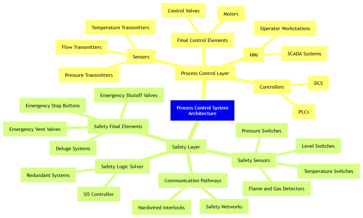
Like a BPCS, a SIS consists of three main components, but with a heightened focus on reliability and fault tolerance:
- Sensors: These detect the hazardous process condition (e.g., high temperature, high pressure, abnormal level). Unlike standard process sensors, SIS sensors are often redundant (multiple sensors measuring the same variable) and designed for high reliability and diagnostic coverage. Examples include safety-rated pressure transmitters, temperature sensors, or flame detectors.
- Logic Solver: This is the “brain” of the SIS, receiving signals from the sensors and executing the programmed safety logic to determine if a safety action is required.
- Safety PLCs: Specialised programmable logic controllers designed for safety applications. They have built-in diagnostics, redundancy, and certified safety functions. They are distinct from standard industrial PLCs in their architecture and programming environment.
- Relay-based Logic: For simpler, older systems, hardwired relays can form the logic solver, though these are less common in modern complex systems.
- Final Elements: These are the devices that execute the safety action to bring the process to a safe state. They often include:
- Safety Shutoff Valves (SSVs): Designed to rapidly close or open to isolate flow, vent pressure, or divert material away from a hazardous area. They are often “fail-safe,” meaning they move to a safe position (e.g., fully closed) upon loss of power or signal.
- Emergency Shutdown (ESD) Pumps/Motors: Devices that can be stopped or started to mitigate a hazard.
- Relief Valves: While passive, they are often considered as a final layer of protection in conjunction with SIS.
SIS vs BPCS (Basic Process Control System)
| Feature | SIS | BPCS |
|---|---|---|
| Purpose | Safety | Control |
| Priority | High (fail-safe) | Operational performance |
| Redundancy | Yes (often 2oo3, 1oo2) | Not always |
| Standards | IEC 61508, IEC 61511 | ISA-88, ISA-95 |
Safety Integrity Level (SIL)
A crucial concept in SIS is the Safety Integrity Level (SIL). SIL is a measure of the probability of a safety instrumented function (SIF) failing to perform its intended safety function when required. It quantifies the risk reduction provided by a SIF.
There are four SIL levels, ranging from SIL 1 (lowest integrity, least risk reduction) to SIL 4 (highest integrity, greatest risk reduction):
- SIL 1: A relatively low level of risk reduction, suitable for minor hazards.
- SIL 2: A moderate level of risk reduction, common for significant hazards.
- SIL 3: A high level of risk reduction, typically applied to major hazards with potentially severe consequences.
- SIL 4: An extremely high level of risk reduction, reserved for the most catastrophic hazards, often requiring very complex and highly redundant systems (rare in practice).
Key Components of SIS
- Sensors: Detect unsafe conditions (e.g., high pressure, high temperature)
- Logic Solvers: Evaluate sensor inputs and determine actions (e.g., safety PLCs)
- Final Elements: Devices like ESD (Emergency Shut Down) valves, motor trips
| SIL Level | Risk Reduction Factor | Probability of Failure on Demand |
|---|---|---|
| SIL 1 | 10 – 100 | ≥ 10⁻² to < 10⁻¹ |
| SIL 2 | 100 – 1,000 | ≥ 10⁻³ to < 10⁻² |
| SIL 3 | 1,000 – 10,000 | ≥ 10⁻⁴ to < 10⁻³ |
| SIL 4 | 10,000 – 100,000 | ≥ 10⁻⁵ to < 10⁻⁴ |
Achieving a specific SIL requires a combination of high-reliability components, redundancy, diagnostics, and rigorous testing.
The target SIL for each SIF is determined during the hazard and risk assessment phase, based on the severity of potential consequences and the likelihood of the hazardous event occurring without the SIF. Achieving a particular SIL requires specific design architectures, component selection (certified safety-rated devices), testing regimes, and maintenance practices.
Importance of Functional Safety Culture
Implementing SIS is not just about installing hardware and software; it requires a strong functional safety culture within an organisation. This includes:
- Competent Personnel: Ensuring that engineers, technicians, and operators involved in SIS have the necessary training and expertise.
- Robust Procedures: Establishing clear procedures for design, installation, testing, maintenance, and modification of SIS.
- Documentation: Meticulous documentation of the safety life cycle, including SRS, design documents, test reports, and maintenance logs.
- Regular Audits: Periodic independent audits to ensure compliance with standards and internal procedures.
Safety Instrumented Systems are a non-negotiable aspect of modern industrial safety, providing the ultimate safeguard against the inherent risks of complex industrial processes. Their rigorous design and operational requirements reflect the critical role they play in protecting lives, assets, and the environment.
Functional Safety Lifecycle
Outlined in IEC 61511, the lifecycle includes:
- Hazard and Risk Assessment
- Safety Requirements Specification
- SIS Design and Engineering
- Installation and Commissioning
- Operation and Maintenance
- Periodic Proof Testing
- Decommissioning
Conclusion
The journey through industrial automation and instrumentation reveals a complex yet fascinating interplay of technology, engineering, and safety. From the foundational principles of automation that drive efficiency and consistency, to the precise measurements provided by instrumentation in demanding environments like manufacturing and oil & gas, these disciplines are fundamental to modern industry.
The advent of the Industrial Internet of Things and smart instrumentation has ushered in an era of unprecedented connectivity and data-driven insights, enabling predictive maintenance, remote operations, and continuous optimisation. Crucially, underlying all these advancements is the unwavering commitment to safety, exemplified by Safety Instrumented Systems (SIS), which stand as independent guardians against potential catastrophic failures.
As industries continue to evolve, integrating cutting-edge technologies like artificial intelligence, machine learning, and advanced analytics, the roles of automation and instrumentation will only grow in importance. They are not merely tools but strategic enablers that ensure processes are not only productive and efficient but also inherently safe and resilient in the face of ever-increasing complexity. Embracing these technologies and understanding their nuances is key for any organisation striving for operational excellence and a secure future.
Further Reading & References
- International Society of Automation (ISA) – www.isa.org
- IEC 61511 Standard: Functional Safety – Safety Instrumented Systems for the Process Industry Sector
- OPC Foundation – www.opcfoundation.org
- National Instruments – www.ni.com
- Emerson Process Management – Instrumentation Guides