Control Valves: Comprehensive Guide to Industrial Flow Control Systems
Control Valves: Comprehensive Guide to Industrial Flow Control Systems
Control valves are fundamental components in industrial process control systems, serving as the final control elements that regulate the flow of fluids (liquids, gases, or steam) through piping systems. These devices respond to control signals from process controllers to maintain desired process variables such as flow rate, pressure, temperature, or level. The importance of control valves cannot be overstated, as they directly influence process efficiency, safety, and product quality across industries ranging from oil and gas to pharmaceuticals and water treatment.
This comprehensive guide explores the essential aspects of control valves, including their types, characteristics, sizing methodologies, and actuation systems. Understanding these components is crucial for engineers, technicians, and operators involved in process control and instrumentation.

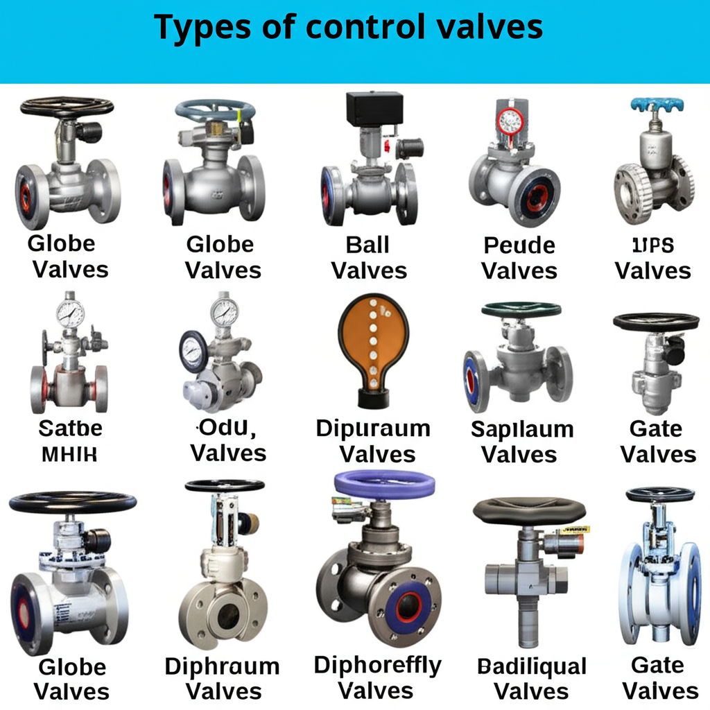
Types of Control Valves
Control valves come in various designs, each optimised for specific applications and operating conditions. The three most common types are globe valves, ball valves, and butterfly valves, each offering unique advantages and characteristics.
Globe Valves
Globe valves are among the most widely used control valves in industrial applications due to their excellent throttling capabilities and precise flow control characteristics. These valves feature a movable disk or plug that regulates flow by varying the area of the flow passage.
    [Inlet]
       ↓
   ┌─────────────┐
   │    ┌─┐      │  ← Actuator
   │    │ │      │
   │ ┌──┴─┴──┐   │  ← Valve Stem
   │ │ Plug  │   │
   │ │   ↓   │   │
   │ └───────┘   │  ← Valve Body
   │      ═══    │  ← Flow Path
   └─────────────┘
       ↓
   [Outlet]

   Figure 1: Globe Valve Cross-Section
Key characteristics of globe valves:
- Linear flow characteristics: Provide a proportional relationship between valve opening and flow rate.
- Excellent shutoff capability: Achieve tight sealing when fully closed.
- High pressure drop: The tortuous flow path creates significant pressure loss.
- Bi-directional flow: Can handle flow in either direction, though a preferred flow direction is typically specified.
- Precise control: Suitable for applications requiring fine flow modulation.
Applications: Globe valves are ideal for applications requiring precise flow control, such as steam control, chemical processing, and water treatment systems where accurate throttling is essential.
Ball Valves
Ball valves utilize a spherical closure element with a bore through its center to control flow. The ball rotates within the valve body to align or misalign the bore with the pipeline, providing quick opening and closing action.
   Closed Position        Open Position

   ┌─────────────┐       ┌─────────────┐
   │    ┌─┐      │       │    ┌─┐      │
   │    │●│      │       │    │○│      │
   │ ┌──┴─┴──┐   │       │ ┌──┴─┴──┐   │
   │ │  ███  │   │       │ │  ○○○  │   │
   │ │  ███  │   │       │ │  ○○○  │   │
   │ │  ███  │   │       │ │  ○○○  │   │
   │ └───────┘   │       │ └───────┘   │
   │      ═══    │       │      ═══    │
   └─────────────┘       └─────────────┘

   Figure 2: Ball Valve Operation
Key characteristics of ball valves:
- Quick operation: 90-degree rotation for full open to full close.
- Low pressure drop: Straight-through flow path minimises pressure loss.
- Excellent sealing: Metal-to-metal or soft seat sealing provides bubble-tight shutoff.
- Limited throttling capability: Not ideal for precise flow modulation.
- High flow capacity: Full bore design allows maximum flow rates.
Applications: Ball valves are commonly used in on/off applications, isolation services, and situations where low pressure drop is critical, such as gas pipeline systems and high-volume liquid applications.
Butterfly Valves
Butterfly valves employ a circular disc that rotates about a shaft perpendicular to the flow direction. The disc position determines the flow area and, consequently, the flow rate through the valve.
   Fully Open           Partially Open        Fully Closed

   ┌─────────────┐      ┌─────────────┐      ┌─────────────┐
   │      │      │      │      /      │      │      ─      │
   │      │      │      │     /       │      │      ─      │
   │══════│══════│      │════/════════│      │      ─      │
   │      │      │      │   /         │      │      ─      │
   │      │      │      │  /          │      │      ─      │
   └─────────────┘      └─────────────┘      └─────────────┘

   Figure 3: Butterfly Valve Positions
Key characteristics of butterfly valves:
- Compact design: Minimal space requirements and lightweight construction.
- Cost-effective: Lower initial cost compared to globe and ball valves.
- Quick operation: 90-degree rotation for full stroke.
- Moderate pressure drop: Disc creates some flow obstruction even when fully open.
- Good throttling capabilities: Suitable for modulating control applications.
Applications: Butterfly valves are widely used in large diameter applications, HVAC systems, water treatment plants, and applications where space and weight constraints are important considerations.
Valve Characteristics
Understanding valve characteristics is essential for proper valve selection and system design. Two primary characteristics define valve performance: flow versus pressure relationship and flow versus stroke relationship.
Flow vs. Pressure Characteristics
The relationship between flow rate and pressure drop across a valve is fundamental to understanding valve behavior and system performance. This relationship is typically expressed through the valve flow coefficient (Cv) and follows specific mathematical relationships.
   Flow Rate vs Pressure Drop

   Q │
     │     ●
     │    ●
     │   ●
     │  ●
     │ ●
     │●
     └────────────────────── ΔP

   Q ∝ √ΔP (for liquids)
   Q ∝ √(ΔP × P₁) (for gases)

   Figure 4: Flow vs. Pressure Characteristics
Key relationships:
- Liquid flow: Flow rate is proportional to the square root of pressure drop.
- Gas flow: Flow rate depends on both pressure drop and inlet pressure.
- Choked flow: Maximum flow rate occurs when pressure drop reaches a critical ratio.
- Cavitation: Can occur in liquid applications when local pressure drops below vapor pressure.
Flow vs. Stroke Characteristics
The flow versus stroke characteristic describes how the flow rate changes with valve opening position. This relationship is crucial for control system design and determines how the valve responds to control signals.
   Flow Characteristics

   100% │     Linear    Equal %    Quick Open
        │       /         ●           ●
   Flow │      /         ● ●         ● ●
    %   │     /         ●   ●       ●   ●
        │    /         ●     ●     ●     ●
        │   /         ●       ●   ●       ●
        │  /         ●         ● ●         ●
      0%└─────────────────────────────────────
        0%    25%    50%    75%    100%
                 Valve Opening %

   Figure 5: Inherent Flow Characteristics
Types of flow characteristics:
- Linear: Flow rate changes proportionally with valve opening.
- Equal percentage: Equal increments of valve travel produce equal percentage changes in flow.
- Quick opening: Large flow changes occur with small valve movements near the closed position.
- Modified parabolic: Combination characteristics for specific applications.
Valve Sizing and Selection
Proper valve sizing is critical for optimal system performance, ensuring adequate flow capacity while maintaining controllability and avoiding issues such as cavitation, flashing, or noise. The sizing process involves calculating the required valve flow coefficient (Cv) based on process conditions.
Sizing Methodology
The fundamental equation for valve sizing varies depending on the fluid type and operating conditions:
   Liquid Sizing Equation:

   Cv = Q × √(SG/ΔP)

   Where:
   Cv = Valve flow coefficient
   Q = Flow rate (GPM)
   SG = Specific gravity
   ΔP = Pressure drop (PSI)

   Gas Sizing Equation:

   Cv = Q × √(SG × T)/(520 × P₁ × Y)

   Where:
   Q = Flow rate (SCFH)
   T = Temperature (°R)
   P₁ = Inlet pressure (PSIA)
   Y = Expansion factor
Critical considerations in valve sizing:
- Safety factors: Typically 10-25% oversizing to account for uncertainties.
- Turndown ratio: Range of controllable flow rates.
- Pressure recovery: Valve’s ability to recover pressure downstream.
- Noise prediction: Aerodynamic noise generation in gas applications.
- Cavitation index: Potential for cavitation in liquid services.
Selection Criteria
Valve selection involves evaluating multiple factors beyond sizing calculations:
- Process conditions: Temperature, pressure, flow rates, and fluid properties.
- Control requirements: Accuracy, response time, and stability needs.
- Safety considerations: Fire-safe design, fail-safe positions, and emergency shutdown.
- Environmental factors: Corrosion resistance, temperature extremes, and regulatory compliance.
- Economic factors: Initial cost, maintenance requirements, and lifecycle costs.
Valve Actuators
Valve actuators provide the necessary force and motion to operate control valves in response to control signals. The choice of actuator type depends on application requirements, available utilities, and performance specifications.
Pneumatic Actuators
Pneumatic actuators are the most common type in process control applications, utilizing compressed air to generate the force needed for valve operation.
   Pneumatic Actuator Cross-Section

   ┌─────────────────────────┐
   │     Air Supply          │ ← Control Signal (3-15 PSI)
   ├─────────────────────────┤
   │        Spring           │ ← Return Spring
   ├─────────────────────────┤
   │      Diaphragm          │ ← Pressure-sensitive element
   ├─────────────────────────┤
   │    Actuator Stem        │
   └───────────┼─────────────┘
               │
               ▼ to Valve

   Figure 6: Pneumatic Diaphragm Actuator
Advantages of pneumatic actuators:
- High power-to-weight ratio: Generate significant force with relatively light components.
- Intrinsic safety: Safe for use in hazardous environments.
- Fast response: Quick reaction to control signal changes.
- Fail-safe operation: Spring return provides predictable failure mode.
- Simple maintenance: Few moving parts and robust design.
Electric Actuators
Electric actuators use electric motors and gear reduction systems to provide precise positioning and high torque capabilities.
   Electric Actuator Components

   ┌─────────────────┐
   │  Control Unit   │ ← Microprocessor control
   ├─────────────────┤
   │   AC/DC Motor   │ ← Prime mover
   ├─────────────────┤
   │  Gear Reducer   │ ← Torque multiplication
   ├─────────────────┤
   │ Position Sensor │ ← Feedback device
   └─────────┼───────┘
             │
             ▼ to Valve

   Figure 7: Electric Actuator System
Advantages of electric actuators:
- Precise positioning: Excellent repeatability and accuracy.
- High torque output: Suitable for large or high-pressure applications.
- Remote operation capability: Can be controlled from great distances.
- Diagnostic capabilities: Built-in monitoring and troubleshooting features.
- Energy efficiency: Power consumption only during movement.
Hydraulic Actuators
Hydraulic actuators utilize pressurized hydraulic fluid to generate extremely high forces, making them suitable for heavy-duty applications.
   Hydraulic Actuator System

   [Hydraulic    ┌─────────────┐    [Control
    Supply] →    │   Cylinder  │ ←   Valve]
                 │     ┌───┐   │
                 │     │ P │   │    P = Piston
                 │     │ I │   │    I = Piston Rod
                 │     │ S │   │    S = Seal
                 │     │ T │   │    T = Stem
                 │     │ O │   │    O = Connection
                 │     │ N │   │    N = to Valve
                 └─────┴───┴───┘

   Figure 8: Hydraulic Piston Actuator
Advantages of hydraulic actuators:
- Extremely high force: Highest power-to-weight ratio among actuator types.
- Precise control: Excellent speed and position control.
- Compact design: High force in small packages.
- Variable speed operation: Smooth motion control over wide speed ranges.
- Overload protection: Built-in pressure relief prevents damage.
Conclusion
Control valves represent critical components in modern industrial process control systems, requiring careful consideration of type selection, characteristic analysis, proper sizing, and appropriate actuation methods. The choice between globe, ball, and butterfly valves depends on specific application requirements, while understanding flow characteristics ensures optimal control performance. Proper sizing methodology prevents operational issues and ensures system efficiency, while actuator selection must balance performance requirements with practical considerations such as safety, maintenance, and cost.
As industries continue to evolve toward greater automation and precision control, the importance of understanding these fundamental aspects of control valve technology becomes increasingly critical for engineers and technicians involved in process control and instrumentation. Successful implementation requires comprehensive analysis of all these factors to achieve reliable, efficient, and safe process control operations.