
The Blueprint of Power: Delving into Core Electrical Engineering Concepts

Electrical engineering is the bedrock upon which our modern, electrified world is built. It’s a discipline that transforms abstract scientific principles into tangible solutions, from the colossal power grids that span continents to the microscopic circuits within our smartphones. While the previous sections touched upon the practical applications of electricity, this section delves into the theoretical and analytical underpinnings that enable engineers to design, optimise, and troubleshoot complex electrical systems.
For aspiring electrical engineers, seasoned professionals, or simply those with a keen interest in the science of electricity, understanding these core concepts is paramount. We’ll explore the often-misunderstood power factor, the critical analyses of short-circuit and load flow, the meticulous art of substation design, and the fundamental principles governing electrical machines and power systems. This journey into the heart of electrical engineering will illuminate the intellectual rigour and innovation required to harness and manage electrical energy effectively.
Optimising Efficiency: Power Factor and Correction Techniques

One of the most crucial yet frequently misunderstood concepts in electrical engineering, particularly in industrial settings, is Power Factor (PF). It’s a measure of how effectively electrical power is being utilised by a load.
Understanding Power: To truly grasp power factor, it’s essential to differentiate between three types of power in AC circuits:
- Active Power (P): Also known as real power, working power, or true power, measured in kilowatts (kW). This is the useful power that performs actual work, like turning a motor, heating a coil, or lighting a lamp.
- Reactive Power (Q): Measured in kilovolt-ampere reactive (kVAr). This power does no useful work but is necessary to establish and maintain the magnetic fields required by inductive loads (e.g., motors, transformers, fluorescent lamp ballasts). It essentially “sloshes” back and forth between the source and the load.
- Apparent Power (S): Measured in kilovolt-amperes (kVA). This is the total power delivered by the utility, which is the vector sum of active and reactive power.
Power Factor Defined: Power factor is the ratio of active power to apparent power:PF=Apparent Power (kVA)Active Power (kW)
It’s a dimensionless number between 0 and 1 (or 0% and 100%). A power factor close to 1 (or 100%) indicates highly efficient use of power, meaning most of the delivered current is doing useful work. A low power factor (e.g., 0.7 or 70%) indicates a large proportion of reactive power, meaning more current is flowing through the system than is actually being converted into useful work.
Consequences of Low Power Factor: A low power factor is detrimental for several reasons:
- Increased Current: For the same amount of active power, a lower power factor means higher apparent power, which translates to higher current draw.
- Increased Losses: Higher current leads to increased I2R (resistive) losses in cables, transformers, and generators, meaning more energy is wasted as heat.
- Voltage Drops: Excessive reactive current causes greater voltage drops, especially in long feeder lines, potentially affecting equipment performance.
- Larger Equipment Sizing: Utilities and industries must install larger capacity transformers, switchgear, and cables to handle the increased apparent power, leading to higher capital costs.
- Penalties: Electricity suppliers often impose penalties on industrial and commercial customers with low power factors to encourage efficient energy use.
Power Factor Correction Techniques: The goal of power factor correction (PFC) is to improve the power factor, typically by reducing the reactive power component.
- Capacitor Banks: The most common method. Inductive loads “consume” reactive power, so by adding capacitors (which “supply” reactive power) in parallel with the inductive loads, the reactive power drawn from the utility is reduced. These can be fixed, automatically switched, or tuned capacitor banks depending on the load variation and harmonic content.
- Synchronous Condensers: Large synchronous motors operating without a mechanical load, specifically designed to draw or supply reactive power to the system. Used in large-scale power systems.
- Active Power Factor Correctors (APFCs): Increasingly used in modern electronic loads, these electronic circuits dynamically control the current waveform to ensure it remains in phase with the voltage, achieving near-unity power factor.
Implementing effective power factor correction leads to reduced energy bills, lower transmission losses, improved voltage regulation, and extended equipment lifespan.
Safeguarding and Sizing: Short-Circuit and Load Flow Analysis
Two fundamental analytical tools in electrical engineering, particularly in power system design and operation, are Short-Circuit Analysis and Load Flow Analysis.
Short-Circuit Analysis (Fault Analysis): A short circuit (or fault) occurs when an abnormal low-resistance path is created between two or more conductors, allowing a dangerously high current to flow. Short-circuit analysis is the process of calculating the magnitude of these fault currents at various points in a power system.
Why it’s Crucial:
- Equipment Sizing: Circuit breakers, fuses, and switchgear must be rated to safely interrupt the maximum possible short-circuit current without damage. This analysis helps determine the required interrupting capacity.
- Protective Device Coordination: The analysis helps engineers select and set protective relays and fuses to ensure that only the faulty section of the system is isolated, minimising disruption to healthy parts.
- Arc Flash Hazard Assessment: High fault currents lead to arc flashes, dangerous explosions of electrical energy. Short-circuit analysis provides the data needed to calculate incident energy levels and implement safety measures (e.g., PPE requirements).
- Equipment Withstand Ratings: Busbars, cables, and transformers must be able to withstand the mechanical and thermal stresses caused by fault currents until protective devices operate.
The analysis involves using impedance models of all system components (generators, transformers, lines) and applying fault conditions (e.g., three-phase fault, single-line-to-ground fault) at various buses. Specialized software (like ETAP, DIgSILENT PowerFactory, PSS/E) is essential for complex systems.
Load Flow Analysis (Power Flow Analysis): Load flow analysis determines the steady-state operating conditions of a power system under normal or specified load conditions. It calculates the voltage magnitudes and angles at each bus, and the active and reactive power flows through all transmission lines, transformers, and feeders.
Why it’s Crucial:
- System Planning: Essential for planning future expansion, assessing the impact of new loads or generation, and identifying bottlenecks.
- Voltage Profile Assessment: Ensures that voltage levels throughout the system remain within acceptable limits for proper equipment operation.
- Power Loss Calculation: Quantifies active and reactive power losses in transmission lines and transformers.
- Optimal Power Flow: Can be extended to optimise system operation, minimise losses, or reduce operating costs.
- Reactive Power Management: Helps determine the optimal placement and sizing of reactive power compensation devices (e.g., capacitor banks) to maintain voltage stability.
Load flow analysis uses complex iterative numerical methods to solve a set of non-linear algebraic equations derived from Kirchhoff’s laws for each bus in the system. Like short-circuit analysis, it heavily relies on sophisticated software tools.
Both analyses are indispensable for the safe, reliable, and economic design and operation of any modern power system.
The Art of Precision: Electrical Design Calculations using Software
The complexity of modern electrical systems, from industrial plants to large commercial buildings, makes manual design calculations impractical and prone to error. This has led to the widespread adoption of specialized Electrical Design Software that streamlines and enhances the precision of engineering tasks.
Key software tools used in electrical design include:
- ETAP (Electrical Transient Analyzer Program): A comprehensive suite for power system analysis, simulation, and operation. ETAP is widely used for:
- Load flow analysis
- Short-circuit analysis
- Arc flash analysis
- Protective device coordination
- Motor starting analysis
- Harmonic analysis
- Transient stability studies
- Cable sizing and voltage drop calculations. It allows engineers to model an entire electrical network, run various scenarios, and generate detailed reports, significantly improving safety and efficiency.
- AutoCAD Electrical: A powerful CAD software specifically designed for creating electrical control schematics, panel layouts, and wiring diagrams. It offers:
- Libraries of standard electrical symbols.
- Automated numbering of wires and components.
- Automatic generation of bills of material and terminal strip drawings.
- Cross-referencing for components. This software drastically reduces design time, minimises errors, and ensures consistency in electrical documentation.
- Revit MEP: Part of Autodesk’s Building Information Modelling (BIM) suite, Revit MEP (Mechanical, Electrical, and Plumbing) allows electrical engineers to design and model electrical systems within a 3D building environment. It enables:
- Accurate spatial coordination with other disciplines (architectural, structural, mechanical).
- Clash detection to identify interferences.
- Automated cable routing and conduit sizing.
- Photometric analysis for lighting design. Revit MEP facilitates a more integrated and collaborative design process, reducing errors during construction.
- Dialux/Relux: Dedicated lighting design software used for:
- Calculating light levels and uniformity in spaces.
- Selecting appropriate luminaires.
- Producing detailed lighting layouts and visualisations. These tools ensure optimal illumination while considering energy efficiency.
- Dedicated Cable Sizing Software: Tools that help engineers select the correct cable size based on current carrying capacity, voltage drop, and short-circuit withstand, adhering to relevant national standards (e.g., BS 7671 for UK, NEC for USA).
The adoption of these software tools has transformed electrical engineering, enabling engineers to tackle more complex projects with greater accuracy, speed, and safety.
The Hub of the Grid: Substation Design Basics
Substations are critical nodes in an electrical power system, acting as intermediaries between the generation, transmission, and distribution networks. They are facilities where voltage is transformed from one level to another (either stepped up for long-distance transmission or stepped down for local distribution), and where power can be switched, controlled, and protected.
Key Functions of a Substation:
- Voltage Transformation: Using transformers to step up or step down voltage levels.
- Switching: Connecting or disconnecting lines and equipment from the system for operational flexibility, maintenance, or fault isolation using circuit breakers and disconnectors.
- Protection: Housing protective relays, current transformers (CTs), and potential transformers (PTs) to detect faults and isolate faulty sections of the grid.
- Voltage Regulation: Maintaining stable voltage levels within specified limits, often using tap changers on transformers or reactive power compensation devices.
- Monitoring and Control: Modern substations incorporate SCADA systems for remote monitoring and control.
Basic Components of a Substation:
- Power Transformers: The core of the substation, performing voltage conversion.
- Circuit Breakers: High-voltage switching devices capable of interrupting fault currents.
- Disconnectors (Isolators): Mechanical switches used to physically isolate equipment for maintenance, typically operated only when the circuit is de-energised.
- Busbars: Rigid or flexible conductors that connect various components within the substation, acting as common connection points.
- Current Transformers (CTs) and Potential Transformers (PTs): Instrument transformers that step down high currents and voltages to safe, measurable levels for metering and protective relays.
- Protective Relays: Intelligent devices that detect abnormal conditions (e.g., overcurrent, overvoltage, undervoltage) and issue trip signals to circuit breakers.
- Surge Arresters (Lightning Arresters): Protect equipment from overvoltages caused by lightning strikes or switching surges.
- Control Building: Houses control panels, relay panels, communication equipment, and DC battery backup systems for control power.
- Grounding System: An extensive network of buried conductors to ensure safety and provide a low-impedance path for fault currents.
Design Considerations: Substation design is a highly specialised field that considers factors such as:
- Voltage Levels: Dictates insulation requirements and clearances.
- Load Requirements: Determines transformer and equipment sizing.
- Fault Levels: Influences circuit breaker interrupting capacities.
- Reliability and Redundancy: Often involves redundant equipment or alternative feeding arrangements.
- Environmental Factors: Space constraints, climate, seismic activity, and noise considerations.
- Safety: Strict adherence to safety clearances and grounding practices.
- Future Expansion: Design often incorporates provisions for future growth.
Substations are complex engineering marvels, essential for the reliable and efficient delivery of electricity to homes and industries.
The Heart of Electromechanical Conversion: Electrical Machine Principles: Motors, Generators, Transformers
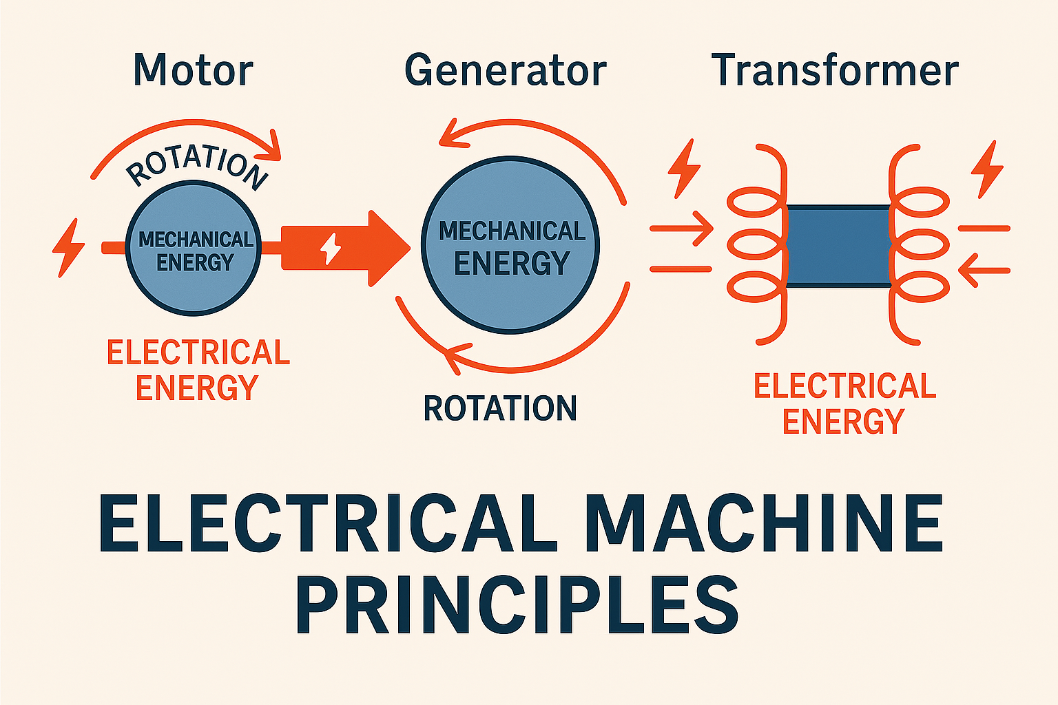
Electrical machines are devices that convert energy from one form to another, specifically between electrical and mechanical energy. Understanding their fundamental principles is central to electrical engineering. We’ve touched on transformers, but let’s briefly revisit them in context and add motors and generators.
- Motors (Electrical to Mechanical):
- Principle: Operate on the principle of electromagnetism. When current flows through a conductor in a magnetic field, it experiences a force (Lorentz force). In a motor, coils (windings) interact with a magnetic field (produced by permanent magnets or electromagnets) to produce continuous rotational motion (torque).
- Types:
- DC Motors: Rely on commutators for continuous rotation, used where precise speed control is needed (e.g., electric vehicles, industrial robots).
- AC Motors:
- Induction Motors (Asynchronous Motors): The most common industrial motor. Their rotor current is induced by the stator’s rotating magnetic field. They are robust, reliable, and relatively inexpensive.
- Synchronous Motors: Rotor rotates at precisely the same speed as the stator’s magnetic field (synchronous speed). Used where constant speed is critical or for power factor correction (as synchronous condensers).
- Applications: Driving pumps, fans, conveyors, compressors, machine tools, and virtually every piece of automated equipment in industry.
- Generators (Mechanical to Electrical):
- Principle: Operate on Faraday’s Law of Electromagnetic Induction. When a conductor moves through a magnetic field, or a magnetic field changes through a coil, a voltage (and thus current, if a circuit is closed) is induced in the conductor. Mechanical energy (e.g., from steam turbines, wind turbines, hydro turbines, diesel engines) is used to rotate coils within a magnetic field or vice-versa, generating electricity.
- Types:
- DC Generators (Dynamos): Use commutators to produce DC output. Less common for large-scale power generation today.
- AC Generators (Alternators): The primary source of electrical power worldwide. Produce AC output, often three-phase.
- Applications: Power plants (thermal, hydro, nuclear, wind), standby generators, vehicle alternators.
- Transformers (Electrical to Electrical):
- Principle: Utilise mutual inductance between two or more windings to transfer electrical energy from one circuit to another without a direct electrical connection, typically changing voltage and current levels.
- Applications: Essential for efficient transmission and distribution of electricity at various voltage levels throughout the power grid.
A deep understanding of these machines, their construction, operating characteristics, and control methods is fundamental for electrical engineers involved in power generation, transmission, distribution, and industrial applications.
The Grand Architecture: Power Generation and Transmission Systems Overview
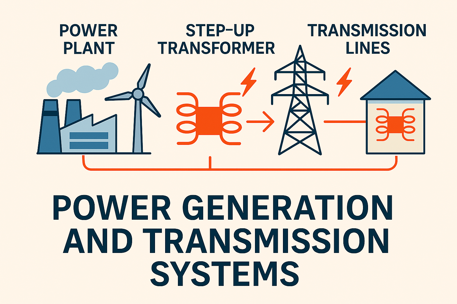
The process of delivering electricity from its source to your home or factory is a monumental engineering feat involving a vast and intricate network of interconnected systems. This is the realm of Power Generation and Transmission Systems.
1. Power Generation:
- Thermal Power Plants: (Coal, Gas, Oil) – Boil water to create steam, which drives turbines connected to alternators (generators).
- Hydroelectric Power Plants: Use the kinetic energy of flowing or falling water to spin turbines.
- Nuclear Power Plants: Use controlled nuclear fission to generate heat, which boils water to produce steam for turbines.
- Renewable Energy Sources: (Solar, Wind, Geothermal, Biomass) – Convert natural forces directly into electricity or use them to drive generators.
- Co-generation/Combined Heat and Power (CHP): Generate electricity while simultaneously capturing waste heat for other uses, improving overall efficiency.
2. Transmission System:
- Voltage Step-Up: After generation, voltage is stepped up (e.g., to 132 kV, 275 kV, 400 kV in the UK, or 330 kV in Nigeria) using step-up transformers at the power plant’s switchyard.
- Transmission Lines: High-voltage overhead lines (pylons) or underground cables carry this power over long distances to minimise I2R losses.
- Transmission Substations: Act as junctions, stepping down voltage, switching power between lines, and connecting different parts of the high-voltage network.
- The Grid: The interconnected network of generation plants, transmission lines, and substations that ensures reliable and flexible power delivery across a wide geographical area.
3. Distribution System:
- Distribution Substations: Step down transmission voltages to lower distribution voltages (e.g., from 132 kV to 33 kV or 11 kV).
- Primary Distribution Lines: Carry power from distribution substations to local areas (e.g., communities, industrial estates).
- Distribution Transformers: Step down voltage further to utilisation levels (e.g., 415V three-phase for industrial use, or 230V single-phase for residential use in Nigeria/UK).
- Secondary Distribution Lines: Deliver power from distribution transformers to individual consumers.
Challenges in Power Systems:
- Stability: Maintaining voltage and frequency stability under varying load conditions and disturbances.
- Reliability: Ensuring continuous power supply despite equipment failures or external events.
- Efficiency: Minimising losses during generation, transmission, and distribution.
- Integration of Renewables: Incorporating intermittent renewable sources into the grid.
- Grid Modernisation: Evolving towards smart grids with advanced monitoring, control, and communication capabilities.
This overview highlights the immense scale and complexity of the power system, a testament to the continuous innovation in electrical engineering.
Tapping into Nature’s Bounty: Renewable Energy Systems (Solar, Wind, Hybrid)

The global imperative to combat climate change and achieve energy security has propelled renewable energy systems to the forefront of electrical engineering. These systems harness naturally replenishing sources to generate electricity, offering a sustainable alternative to fossil fuels.
- Solar Power (Photovoltaic – PV Systems):
- Principle: PV cells convert sunlight directly into DC electricity through the photovoltaic effect.
- Components: Solar panels, inverters (DC to AC), mounting structures, wiring, and often battery storage or grid connection.
- Types: Rooftop solar for homes/businesses, large-scale solar farms, building-integrated PV (BIPV).
- Engineering Challenges: Intermittency (day/night, cloudy weather), efficiency of conversion, battery storage solutions, grid integration, land use.
- Wind Power:
- Principle: Wind turbines capture kinetic energy from the wind, spinning blades connected to a generator to produce electricity.
- Components: Blades, rotor, nacelle (housing gearbox and generator), tower, foundation, control systems.
- Types: Onshore wind farms, offshore wind farms (offering higher, more consistent winds but greater installation challenges).
- Engineering Challenges: Wind resource assessment, structural integrity of turbines, grid stability impacts of intermittent generation, noise, visual impact, offshore logistics.
- Hybrid Renewable Energy Systems:
- Principle: Combine two or more renewable energy sources (e.g., solar and wind, or solar and hydro) often with battery storage or a conventional generator backup.
- Benefits: Address the intermittency of individual sources by leveraging their complementary nature (e.g., wind at night, solar during the day). Improves reliability and often reduces reliance on grid or fossil fuels.
- Engineering Challenges: Complex control systems to manage multiple sources, energy storage optimisation, power electronics for seamless integration, economic dispatch.
The engineering of renewable energy systems involves sophisticated power electronics, grid integration studies, resource assessment, mechanical design, and advanced control algorithms to ensure efficiency, reliability, and grid compatibility. It’s a rapidly evolving field driving the energy transition.
Safety and Stability: Earthing System Types and Design
Earthing (Grounding in American English) Systems are fundamental to electrical safety and the reliable operation of electrical equipment. An earthing system provides a low-resistance path for fault currents to dissipate safely into the general mass of the earth, preventing dangerous voltage rises and ensuring protective devices operate correctly.
Key Objectives of Earthing:
- Personnel Safety: Protects people from electric shock by limiting touch and step voltages during a fault.
- Equipment Protection: Limits overvoltages and prevents damage to electrical equipment due to insulation failure, lightning, or switching surges.
- System Operation: Ensures proper operation of protective relays and other control devices by providing a stable reference point and allowing fault currents to flow for detection.
- Lightning Protection: Provides a safe path for lightning discharge currents.
- Static Electricity Control: Dissipates static charges to prevent hazardous accumulation.
Common Earthing System Types (as per IEC 60364 / BS 7671 for UK/Nigeria context): These are classified by letters indicating the relationship of the source and load to earth, and the type of earthing connection:
- TN Systems: The neutral point of the source (transformer) is directly earthed, and the exposed conductive parts of the installation are connected to this earthed neutral.
- TN-C (Terra-Neutral-Combined): Neutral and Protective Earth (PE) conductors are combined into a single conductor (PEN conductor). Simpler but less safe if the PEN conductor breaks. (Less common for new installations).
- TN-S (Terra-Neutral-Separate): Separate neutral (N) and protective earth (PE) conductors are provided throughout the installation. Offers high safety.
- TN-C-S (Terra-Neutral-Combined-Separate): Often called Protective Multiple Earth (PME). The supply network has a combined PEN conductor, but the consumer’s installation uses separate N and PE conductors, with the PEN conductor being earthed at multiple points along the supply. Very common in the UK and Nigeria for residential/commercial.
- TT Systems: The neutral point of the source is directly earthed, but the exposed conductive parts of the installation are connected to an independent earth electrode at the consumer’s premises. This requires Residual Current Devices (RCDs) for shock protection. Common where TN systems are not feasible.
- IT Systems: The neutral point of the source is either unearthed or earthed through a high impedance. Exposed conductive parts of the installation are individually earthed. Used in critical applications (e.g., hospitals, data centres) where continuity of supply is paramount, as a single fault does not immediately cause disconnection.
Earthing System Design: This involves:
- Soil Resistivity Testing: Determines the electrical resistance of the ground, crucial for sizing earth electrodes.
- Earth Electrode Selection: Choosing appropriate electrodes (e.g., earth rods, earth plates, buried strips) and their configuration.
- Earthing Grid Design: For substations and industrial plants, a grid of buried conductors is designed to achieve a low overall earth resistance and control touch/step voltages.
- Bonding: Ensuring all metallic enclosures, conduits, structural steel, and non-current-carrying parts are effectively bonded to the earthing system.
- Calculations: Using software or manual methods to calculate earth resistance, potential rise, and step/touch voltages to ensure compliance with safety limits.
A well-designed and properly maintained earthing system is the cornerstone of electrical safety and operational integrity.
Precision and Control: Electrical Measurement and Instrumentation
Electrical Measurement and Instrumentation are critical aspects of electrical engineering, enabling engineers and technicians to quantify electrical parameters, monitor system performance, diagnose faults, and ensure the safe and efficient operation of electrical systems.
Key Electrical Parameters Measured:
- Voltage: Measured in Volts (V), using voltmeters.
- Current: Measured in Amperes (A), using ammeters (requires the circuit to be opened or a current transformer/clamp meter).
- Resistance: Measured in Ohms (Ω), using ohmmeters (circuit must be de-energised).
- Power: Active power (kW), reactive power (kVAr), apparent power (kVA), measured using wattmeters or power analysers.
- Energy: Measured in kilowatt-hours (kWh) using energy meters (e.g., your electricity meter).
- Frequency: Measured in Hertz (Hz), using frequency meters.
- Power Factor: Measured using power factor meters or calculated from power measurements.
- Insulation Resistance: Measured in megaohms (MΩ) using insulation testers (Meggers) to assess the integrity of insulation.
- Earth Resistance: Measured in Ohms (Ω) using earth resistance testers to check the effectiveness of grounding systems.
Common Instrumentation and Tools:
- Multimeters: Versatile handheld devices for measuring voltage, current, resistance, and continuity.
- Clamp Meters: Allow non-contact measurement of current by clamping around a conductor.
- Oscilloscopes: Display waveforms of voltage and current over time, crucial for analysing transient phenomena, harmonics, and signal integrity.
- Power Quality Analysers: Sophisticated instruments that measure and record various power quality parameters (harmonics, sags, swells, transients, power factor).
- Insulation Testers (Meggers): Apply a high DC voltage to test insulation resistance, indicating its health.
- Earth Resistance Testers: Use various methods (e.g., fall-of-potential) to measure the resistance of an earthing system.
- Thermal Imagers (Infrared Cameras): Detect temperature differences in electrical components, revealing hot spots indicative of loose connections, overloading, or impending failures.
- High-Voltage Testers: Used for dielectric strength tests on cables, switchgear, and transformers.
- Protective Relay Test Sets: Used to test the functionality and settings of protective relays.
Accurate measurement is the foundation of effective electrical engineering. It enables engineers to verify designs, commission systems, perform predictive maintenance, and troubleshoot complex problems, ensuring system reliability and safety.
The Virtual Playground: Circuit Simulation using Multisim or Proteus
Before physical circuits are built, especially for control systems, power electronics, or embedded systems, circuit simulation software provides an invaluable virtual environment for design, testing, and validation. Multisim and Proteus are two popular examples of such software.
Multisim (by NI – National Instruments):
- Focus: Primarily focused on analogue, digital, and power electronics circuit simulation. It’s widely used in academia and industry for circuit design and analysis.
- Features:
- Extensive Component Library: Includes a vast range of active (op-amps, transistors, ICs) and passive components, power devices, and digital logic gates.
- Virtual Instruments: Mimics real-world lab instruments like oscilloscopes, multimeters, function generators, and Bode plotters, allowing users to “measure” simulated circuit behaviour.
- SPICE Simulation Engine: Based on the industry-standard SPICE (Simulation Program with Integrated Circuit Emphasis) engine, providing accurate circuit behaviour analysis.
- Interactive Simulation: Allows real-time interaction with virtual switches, potentiometers, and other controls during simulation.
- Integration with Ultiboard: Can transfer circuit designs directly to Ultiboard for PCB (Printed Circuit Board) layout.
- Applications: Designing and verifying electronic circuits, power supplies, filter circuits, amplifier stages, and basic control circuits.
Proteus (by Labcenter Electronics):
- Focus: Combines circuit simulation with microcontroller simulation and PCB design. It’s particularly popular for embedded systems development.
- Features:
- ISIS (Intelligent Schematic Input System): For drawing electronic schematics and simulating them.
- ARES (Advanced Routing and Editing Software): For PCB layout.
- Microcontroller Simulation: A key differentiator. Proteus allows users to write firmware (e.g., in C or assembly) for popular microcontrollers (e.g., PIC, AVR, ARM Cortex-M) and then simulate the microcontroller’s interaction with the surrounding electronic circuit in real-time. This is immensely powerful for debugging embedded systems.
- Co-simulation: Ability to simulate both analogue/digital electronics and microcontroller code simultaneously.
- Virtual Instruments: Similar to Multisim, it provides virtual oscilloscopes, logic analysers, etc.
- Applications: Designing and simulating microcontroller-based systems, IoT devices, robotics control, and general electronic circuit design.
Benefits of Circuit Simulation:
- Cost Savings: Reduces the need for physical prototypes, saving on component costs and manufacturing time.
- Accelerated Development: Allows for rapid iteration and testing of design ideas.
- Early Error Detection: Identifies design flaws and potential problems before hardware is built.
- Safety: Safely tests circuits that might be dangerous to build physically.
- Learning Tool: Provides a hands-on environment for students and engineers to understand circuit behaviour.
Circuit simulation is an indispensable tool in the modern electrical engineer’s toolkit, enabling efficient, reliable, and cost-effective design processes.