
Educational Resources
Essential Certifications for Electrical Engineers in Nigeria: Boost Your Career
Essential Certifications for Electrical Engineers in Nigeria: Boost Your Career is a topic that deserves...
TAMFIS NIG LTDRC 8067447CAC ACTIVEFinima, Bonny Island, Rivers State

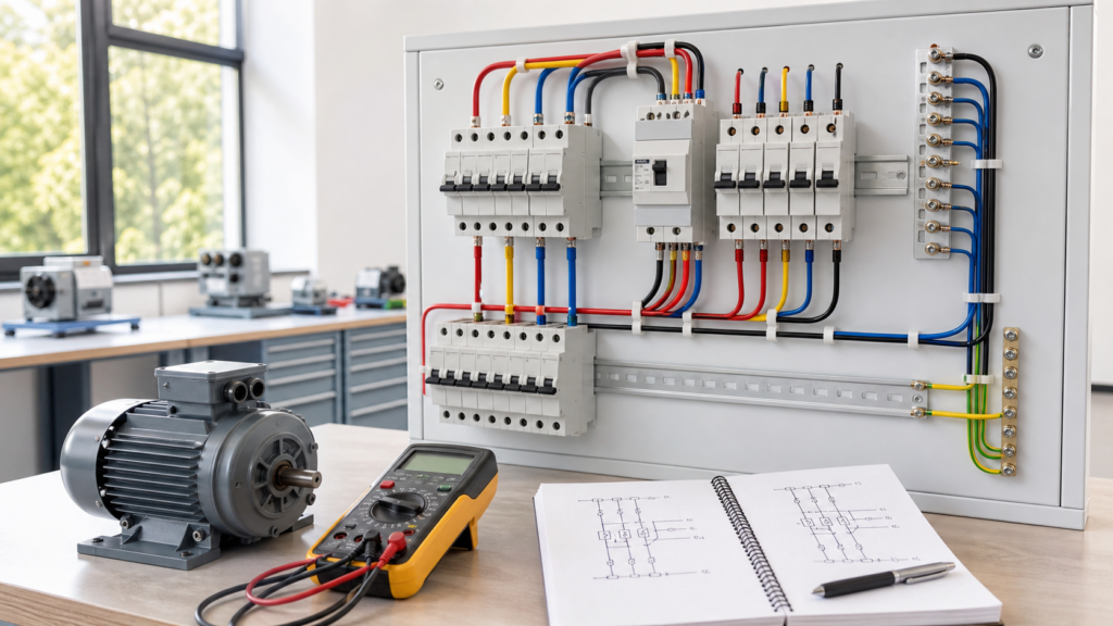
Single-phase and three-phase alternating-current systems deliver electrical energy using the same basic principles, but they behave differently under load. Single-phase supplies are familiar in homes and small premises. Three-phase supplies dominate factories, large commercial buildings, pumps, compressors and other installations where substantial, steady power is required. Understanding the difference is essential before studying motors, distribution boards or industrial control.
This guide explains the concepts, not a procedure for live electrical work. Mains electricity can kill or cause severe burns and fire. Testing, alteration and isolation must be carried out by a competent person using the correct equipment and local rules. The UK Health and Safety Executive recommends securely isolating equipment and proving it dead before work begins; its safe working practices guidance should be treated as a starting point, not replaced by an online article.
In an alternating-current supply, voltage changes polarity in a repeating waveform. Frequency states how many cycles occur each second and is measured in hertz. A sinusoidal waveform is commonly described by its root-mean-square value because that value relates usefully to heating and power. Frequency and nominal voltage vary by country, so equipment must be specified for the actual supply rather than an assumed one.
Real circuits may contain resistance, inductance and capacitance. Current can therefore be displaced in time relative to voltage. The resulting power factor matters because conductors and equipment must carry current even when part of it is not producing useful real power. Engineers distinguish real power in watts, reactive power in volt-amperes reactive and apparent power in volt-amperes.
A typical single-phase circuit has one line conductor and a neutral return, with a protective conductor provided for fault protection where required. The voltage rises and falls as one alternating waveform. This arrangement is economical and entirely suitable for lighting, sockets, electronics, heating and many smaller motors.
For a simple resistive load, power is approximately voltage multiplied by current. With an alternating load that has a power factor below one, real power is voltage multiplied by current and power factor. The calculation is simple; selecting conductors and protection is not. Installation method, ambient temperature, grouping, voltage drop, fault level, disconnection time and the equipment manufacturer’s instructions all affect a real design.
A balanced three-phase source provides three sinusoidal voltages of the same magnitude and frequency, separated from one another by 120 electrical degrees. Because the phases reach their peaks at different times, their combined power is much smoother than the power from one phase. This helps motors produce steady torque and allows efficient transmission of substantial power.
A balanced three-phase load also makes good use of conductor material. In an ideal balanced four-wire system, the three phase currents sum to zero in the neutral. Actual installations may be unbalanced and can contain harmonics, so the neutral must never be treated casually. Designers assess the real load profile and applicable standards.
In a star, or wye, connection, one end of each phase winding meets at a common point. That point may form a neutral. Line voltage is higher than phase voltage by a factor of the square root of three, while line current equals phase current in the balanced ideal case. Star arrangements can provide both line-to-line and line-to-neutral voltages.
In a delta connection, the three phase windings form a closed loop and each line connects to a junction. Line voltage equals phase voltage, while line current is the phase current multiplied by the square root of three in the balanced ideal case. Motors and transformers may use either arrangement according to their winding ratings and duty. The terminals must never be rearranged by guesswork.
For a balanced load, real three-phase power is commonly calculated as the square root of three multiplied by line voltage, line current and power factor. Apparent power omits the power-factor term. These equations help estimate operating demand, but they do not establish cable size, breaker rating or safe isolation. Starting current, duty cycle, harmonics and prospective fault current may be more important than the normal running figure.
Three-phase induction motors are robust because the supply naturally produces a rotating magnetic field. Reversing two phases reverses the field and normally changes the direction of rotation, which can damage a pump or machine if done unintentionally. Phase sequence should therefore be verified during commissioning using an appropriate instrument and an approved procedure.
Loss of a phase or excessive voltage imbalance can overheat a motor even when it continues to turn. Protection may include overload relays, phase-failure monitoring, short-circuit protection and temperature sensing. The correct combination depends on the machine and risk assessment.
An RCD can reduce the risk from some electric shocks but cannot make live work safe or replace earthing, bonding, overcurrent protection and isolation. The HSE’s electrical safety questions and answers explains both the value and limitations of RCD protection.
Begin with low-voltage isolated training equipment. Learn to read circuit diagrams, identify protective and functional conductors, calculate balanced loads and use a multimeter correctly. Then study contactors, overloads, motor starters, transformers and fault protection under qualified supervision. The aim is not merely to memorise formulae, but to connect measurements, diagrams and physical equipment while maintaining safe habits.
Single-phase systems offer simplicity and suit modest loads. Three-phase systems deliver smoother, efficient power for larger installations and rotating machines. Both are safe only when correctly designed, protected, maintained and handled by competent people.
Keep reading
Educational Resources
Essential Certifications for Electrical Engineers in Nigeria: Boost Your Career is a topic that deserves...
Educational Resources
Smart homes have transitioned from futuristic concepts to tangible realities that enhance everyday livin...
Educational Resources
In today's rapidly evolving wor...
TAMFIS NIG LTD
Electrical and instrumentation engineering, bid preparation and consulting, IT and software.