
Powering Progress: A Deep Dive into Industrial Electrical Systems
Industrial environments are the backbone of modern economies, from manufacturing plants and processing facilities to mining operations and power generation stations. Unlike the relatively straightforward single-phase systems found in homes, industrial electrical systems are vast, complex, and operate at significantly higher voltages and currents, demanding a specialized understanding of their design, operation, and maintenance. This section will peel back the layers of these powerful systems, exploring the core concepts that drive industrial productivity, safety, and efficiency.
From the robust three-phase power that energizes colossal machinery to the intricate logic of Programmable Logic Controllers (PLCs) that automate processes, we’ll navigate the essential components and principles that define industrial electrical engineering. Whether you’re an aspiring industrial electrician, a maintenance technician, or simply curious about the immense power grid that supports industry, this guide will illuminate the fascinating world of industrial electricity.
The Workhorse of Industry: Three-Phase Power Systems Explained
While homes typically rely on single-phase alternating current (AC), industrial facilities predominantly utilise three-phase power systems. This isn’t merely an upgrade; it’s a fundamental shift that provides significant advantages for heavy-duty industrial applications.
What is Three-Phase Power? Imagine three separate single-phase AC voltages, each “out of sync” with the others by 120 electrical degrees. This staggered arrangement allows for:
- Constant Power Delivery: Unlike single-phase power, which has pulsating power delivery, three-phase power provides a continuous, smooth flow of power. This is crucial for motors, which receive constant torque, leading to smoother operation, less vibration, and improved efficiency.
- More Efficient Power Transmission: For the same amount of power delivered, three-phase systems require less conductor material than equivalent single-phase systems, making transmission and distribution more economical.
- Self-Starting Motors: Three-phase motors are inherently self-starting, meaning they don’t require auxiliary starting mechanisms, simplifying design and improving reliability.
How it Works: Three separate sinusoidal voltages are generated, typically by a three-phase alternator in a power station. These are transmitted via three “live” conductors (often designated L1, L2, L3 or R, Y, B phases) and sometimes a neutral wire, depending on the configuration (Wye or Delta). Industrial equipment, especially large motors, is designed to tap into this robust three-phase supply, leveraging its inherent balance and efficiency. Understanding phase rotation and phase sequencing is also critical in ensuring motors run in the correct direction and loads are balanced across phases.
The Brains of the Operation: Industrial Control Panels: Design and Wiring
At the heart of almost every automated industrial process lies an industrial control panel. These enclosures house the electrical components that control machinery, processes, and entire production lines. Their design and wiring are meticulous processes, demanding precision, adherence to standards, and a keen understanding of electrical logic.
Key Components within a Control Panel:
- Circuit Breakers: For overcurrent protection of control and power circuits.
- Contactors and Relays: Electrically operated switches used to control high-power loads (like motors) with low-power control signals.
- Overload Relays: Protect motors from drawing excessive current, preventing damage.
- PLCs (Programmable Logic Controllers): The “brain” of the panel, executing control logic (more on this later).
- Terminal Blocks: Provide organized connection points for all internal and external wiring.
- Human-Machine Interfaces (HMIs): Touchscreens or pushbuttons on the panel door allowing operators to interact with the controlled machinery.
- Power Supplies: Convert incoming AC voltage to the lower DC voltages required by control components (e.g., 24V DC for PLCs and sensors).
- Wiring Ducts and Cable Management: Essential for organizing and protecting the vast network of wires within the panel.
Design and Wiring Considerations:
- Layout: Components must be strategically placed for ease of access, heat dissipation, and separation of power and control wiring to minimize interference.
- Wire Sizing and Color Coding: Wires are carefully sized based on current carrying capacity, and consistent color coding (e.g., red for 230V AC, blue for 24V DC, green/yellow for earth) is crucial for safety and troubleshooting.
- Electrical Schematics: Detailed wiring diagrams are indispensable for panel construction, commissioning, and future maintenance.
- Standards Compliance: Panels must adhere to national and international standards (e.g., IEC, UL, NEC) regarding enclosure ratings, component selection, and wiring practices to ensure safety and reliability.
A well-designed and wired control panel is robust, safe, and easily maintainable, forming the central nervous system of industrial automation.
Commanding the Motors: Motor Starters: DOL, Star-Delta, Soft Starters, VFDs
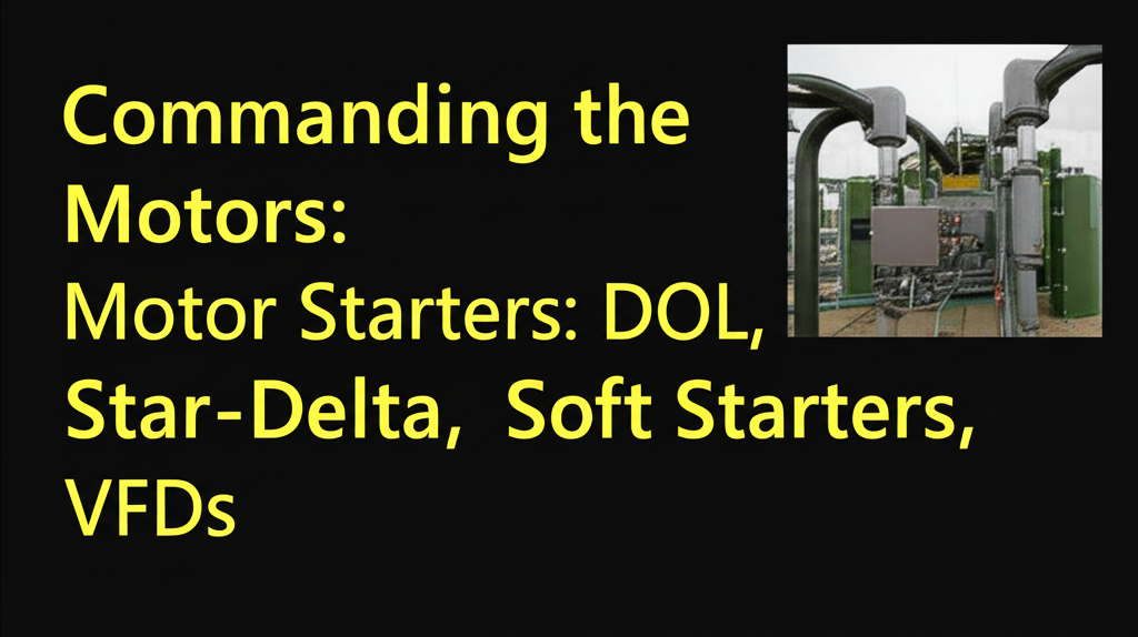
Electric motors are the muscles of industry, powering everything from pumps and conveyors to fans and compressors. However, starting these motors, especially large ones, isn’t as simple as flipping a switch. The sudden inrush of current can cause voltage dips, stress the motor, and strain the power grid. Motor starters are devices designed to control how motors start and run, mitigating these issues.
- Direct-On-Line (DOL) Starter: The simplest and most common starter for smaller motors. It connects the motor directly to the full line voltage, providing maximum starting torque but also the highest starting current (typically 6-8 times the full load current). Suitable where the power supply can handle the inrush and the mechanical load doesn’t require a gentler start.
- Star-Delta (Y-Δ) Starter: Used for medium to large three-phase motors. During starting, the motor windings are connected in a “star” (Y) configuration, which reduces the voltage across each winding and thus limits the starting current to about one-third of the DOL current. Once the motor accelerates to a certain speed, it automatically switches to a “delta” (Δ) configuration for normal full-voltage operation. This provides a gentler start but results in reduced starting torque.
- Soft Starter: An electronic device that gradually increases the voltage to the motor over a set period, resulting in a smooth, controlled acceleration and deceleration. This significantly reduces mechanical stress on the motor and connected equipment, minimizes voltage dips on the supply, and offers more sophisticated control than Star-Delta starters. It uses solid-state electronics (SCRs – Silicon Controlled Rectifiers) to achieve this.
- Variable Frequency Drive (VFD) / Adjustable Speed Drive (ASD): The most advanced motor controller. A VFD converts the incoming AC power to DC, and then inverts it back into a variable-frequency, variable-voltage AC power supply. By controlling the frequency, the VFD precisely controls the motor’s speed, offering unparalleled control over process parameters (e.g., pump flow, fan speed). VFDs also provide “soft starting” and “soft stopping,” significant energy savings (especially for variable torque loads), and advanced protection features. Their initial cost is higher, but the energy savings and process control benefits often justify the investment.
The choice of motor starter depends on the motor size, the application’s requirements for starting torque, current limits, and speed control, as well as energy efficiency considerations.
The Brains of Automation: Introduction to Programmable Logic Controllers (PLCs)
In modern industry, the days of complex, hard-wired relay logic are largely over, replaced by the digital prowess of Programmable Logic Controllers (PLCs). A PLC is a ruggedized industrial computer that automates electromechanical processes, such as controlling machinery on factory assembly lines, amusement rides, or light fixtures.
Key Features and Functionality:
- Inputs: PLCs receive signals from various input devices (e.g., push buttons, limit switches, proximity sensors, temperature sensors) that provide information about the process.
- Processor (CPU): The central processing unit executes the user-programmed logic, constantly monitoring inputs and making decisions based on the program.
- Outputs: Based on the logic, the PLC sends signals to output devices (e.g., motor contactors, solenoids, indicator lights, alarms) to control the machinery.
- Programming Language: PLCs are typically programmed using Ladder Logic (which visually resembles electrical relay diagrams), but also other languages like Function Block Diagram, Structured Text, and Sequential Function Chart.
- Robustness: Designed to withstand harsh industrial environments (vibration, temperature extremes, electrical noise).
- Modularity: Many PLCs are modular, allowing for expansion of input/output (I/O) modules to accommodate varying numbers of sensors and actuators.
How PLCs Revolutionized Industry: PLCs offer immense flexibility. Instead of rewiring physical relays to change control logic, engineers simply modify the program. This drastically reduces downtime for changes, simplifies troubleshooting, and enables more complex and precise control sequences. They are the cornerstone of industrial automation, enabling higher productivity, consistent product quality, and enhanced safety.
Speaking the Language of Control: Control and Relay Logic Diagrams

Before the advent of PLCs, and still fundamental to understanding their underlying principles, control and relay logic diagrams (also known as ladder diagrams or elementary diagrams) were the primary means of designing and documenting industrial control circuits. Even with PLCs, ladder logic directly mimics these traditional relay diagrams.
Components and Interpretation:
- Power Rails: Two vertical lines represent the control power (e.g., 24V DC or 120V AC) – one is the positive/hot rail, the other the negative/neutral/common rail.
- Rungs: Horizontal lines or “rungs” connect the power rails, representing individual control circuits.
- Inputs (Contacts): Represented by symbols that mimic real-world devices like push buttons (normally open – NO, normally closed – NC), limit switches, or overload relay contacts. These are drawn on the left side of the rung.
- Outputs (Coils): Represented by coil symbols, these are the devices that are controlled, such as contactor coils, relay coils, indicator lights, or solenoids. These are drawn on the right side of the rung.
- Logic: The arrangement of contacts and coils dictates the logical sequence of operation. For example, contacts in series represent an “AND” condition (both must be closed for current to flow), while contacts in parallel represent an “OR” condition (either one can be closed).
Purpose and Importance:
- Design Tool: Allows engineers to logically design control sequences before implementation.
- Documentation: Provides a clear, standardized blueprint of the control system for installation and maintenance.
- Troubleshooting: By tracing the logic flow, technicians can quickly pinpoint faulty components or programming errors.
Mastering the interpretation of control and relay logic diagrams is a foundational skill for anyone working with industrial electrical systems, bridging the gap between hardware and automation logic.
The Right Connection: Industrial Wiring Standards and Cable Types
Industrial environments are far more demanding than residential ones, necessitating specialized industrial wiring standards and cable types to ensure reliability, safety, and longevity. The sheer power levels, exposure to chemicals, extreme temperatures, mechanical stress, and electromagnetic interference (EMI) dictate rigorous requirements.
Key Standards and Considerations:
- National and International Codes: Compliance with codes like the NEC (National Electrical Code), IEC (International Electrotechnical Commission), and local Nigerian electrical standards is mandatory. These codes specify everything from conductor sizing to conduit requirements, hazardous area classifications, and cable tray installations.
- Cable Tray Systems: Used extensively in industrial plants to support and organize large quantities of power and control cables, offering protection and accessibility.
- Conduit Systems: Rigid metal conduit (RMC), intermediate metal conduit (IMC), and electrical metallic tubing (EMT) are used to protect wires from physical damage and moisture. Flexible conduits are used for connections to vibrating equipment.
- Cable Glands: Specialized fittings used to terminate cables into enclosures, providing strain relief and maintaining the enclosure’s environmental rating (e.g., dust-tight, watertight).
Common Industrial Cable Types:
- THHN/THWN (Thermoplastic High Heat Nylon/Water Resistant): As in residential, but often in larger gauges and used within conduits.
- XHHW (Cross-linked Polyethylene High Heat Water-Resistant): Excellent insulation properties, often used in conduits for higher voltages.
- SOOW (Service Oil-Resistant, Outer Jacket Weather-Resistant): Flexible, durable cords used for portable equipment in harsh environments.
- Tray Cable (TC): Designed for use in cable trays, often with multiple conductors, suitable for control and power circuits.
- Instrumentation Cable: Shielded cables designed to carry low-level signals from sensors to control systems, minimizing noise interference.
- VFD Cable: Specifically designed to mitigate the harmonic distortion and reflective waves generated by Variable Frequency Drives, protecting the motor and ensuring reliable operation.
- Armored Cable: For robust mechanical protection in exposed or high-risk areas.
The selection of appropriate cable types and adherence to strict wiring standards are paramount for the safe, reliable, and efficient operation of industrial machinery and processes.
Balancing the Grid: Electrical Load Shedding and Management
In large industrial facilities or across a power grid, maintaining a stable power supply is critical. Electrical load shedding and management are strategies employed to balance power generation with demand, especially during peak periods or in the event of supply constraints.
Load Management: This involves actively controlling electrical loads to optimize energy consumption and cost.
- Peak Shaving: Reducing demand during peak tariff hours to lower electricity bills. This might involve shifting non-critical processes to off-peak times or utilizing on-site generation (e.g., standby generators) during these periods.
- Demand Response: Participating in utility programs where facilities agree to reduce load during grid emergencies in exchange for incentives.
- Power Factor Correction: Improving power factor reduces apparent power draw, optimizing the use of existing electrical infrastructure.
Load Shedding: This is a more drastic measure, where certain loads are intentionally disconnected from the power supply to prevent a complete system collapse (blackout) when demand exceeds available generation or during equipment failures.
- Priority Ranking: Critical loads (e.g., safety systems, essential production processes) are assigned higher priority and are shed last. Non-essential loads (e.g., lighting in non-critical areas, non-essential HVAC) are shed first.
- Automated Systems: Many industrial facilities utilize automated load shedding systems integrated with SCADA or plant control systems to quickly and systematically shed loads based on predefined logic.
- Impact: While disruptive, controlled load shedding is far preferable to an uncontrolled blackout, which can cause significant damage to equipment and prolonged downtime.
Effective load shedding and management strategies are vital for ensuring grid stability, optimizing operational costs, and maintaining productivity in industrial settings, particularly in regions with unreliable power grids like parts of Nigeria.
The Electrical Blueprint: Understanding Single-Line Diagrams (SLDs)
For anyone working with industrial electrical systems, understanding Single-Line Diagrams (SLDs) is a foundational skill. An SLD (also known as a one-line diagram) is a simplified schematic representation of a three-phase power system that shows the main electrical components and their interconnections using standard graphical symbols. Unlike multi-line diagrams that show every wire, SLDs focus on the functional flow of power.
Key Information Conveyed by an SLD:
- Power Flow: Shows how electricity is distributed from the utility supply or generator through transformers, switchgear, motor control centers (MCCs), and ultimately to major loads.
- Major Equipment: Represents transformers, circuit breakers, disconnect switches, generators, motors, protective relays, current transformers (CTs), and potential transformers (PTs).
- Voltage Levels: Indicates the voltage at different points in the system.
- Component Ratings: Often includes nominal ratings of equipment (e.g., transformer kVA, breaker amperage, motor horsepower).
- Protective Devices: Shows the location and type of circuit breakers, fuses, and protective relays that safeguard the system.
- Connection Types: May indicate transformer winding configurations (e.g., Delta-Wye).
Why SLDs are Crucial:
- System Overview: Provides a high-level understanding of the entire electrical distribution system.
- Design and Planning: Essential for electrical engineers to design new systems or modify existing ones.
- Troubleshooting: Helps technicians quickly identify the path of power, locate protective devices, and understand where faults might occur.
- Safety: Knowing the system layout and protection points is vital for safe operation and maintenance.
- Communication: Serves as a common language for engineers, technicians, and operators to discuss the electrical system.
Proficiency in reading SLDs is indispensable for electrical engineers and technicians in industrial environments.
The Heart of Power Distribution: Transformer Operation and Maintenance

Transformers are passive electrical devices that transfer electrical energy from one electrical circuit to another, or multiple circuits, through electromagnetic induction. They are fundamental to industrial electrical systems because they efficiently step voltage up or down, allowing power to be transmitted long distances at high voltages (reducing current and resistive losses) and then stepped down to usable voltages at the point of consumption.
How They Work (Simplified): A transformer consists of two or more coils of wire (windings) wrapped around a laminated iron core. When alternating current flows through the primary winding, it creates a fluctuating magnetic field in the core. This changing magnetic field induces an alternating voltage in the secondary winding. The ratio of the number of turns in the primary coil to the secondary coil determines whether the voltage is stepped up or down.
Types Relevant to Industry:
- Step-Up Transformers: Used at power plants to increase voltage for efficient long-distance transmission.
- Step-Down Transformers: Used at substations and industrial facilities to reduce transmission voltage to distribution or utilization voltages (e.g., from 33kV to 11kV, or 11kV to 415V three-phase).
- Isolation Transformers: Used to electrically separate circuits, often for safety or noise reduction.
- Instrument Transformers (CTs & PTs): Used to step down high currents and voltages to safe, measurable levels for protective relays and meters.
Maintenance Considerations: Transformers are highly reliable but require regular maintenance to ensure their longevity and performance:
- Insulating Oil Testing: For oil-filled transformers, regular testing of the dielectric strength, acidity, and moisture content of the oil is critical as oil degrades over time.
- Winding Resistance Tests: To detect loose connections or damaged windings.
- Insulation Resistance Testing (Meggering): To assess the health of winding insulation.
- Cooling System Inspection: Ensuring fans and pumps are operating correctly.
- Tap Changer Maintenance: For transformers with on-load or off-load tap changers, regular inspection and lubrication are needed.
- Thermal Imaging: Identifying hot spots that indicate loose connections or overloading.
- Regular Cleaning: Keeping bushings and cooling fins clean.
Proper transformer maintenance prevents costly failures, ensures continuous power supply, and extends asset life.
Safeguarding Against Disaster: Grounding and Lightning Protection in Industrial Systems

Given the scale and complexity of industrial facilities, grounding and lightning protection systems are far more elaborate and critical than in residential settings. They are paramount for safeguarding personnel, protecting expensive equipment, ensuring operational continuity, and complying with stringent safety regulations.
Industrial Grounding (Earthing) Systems: Beyond basic safety, industrial grounding serves several vital functions:
- Personnel Safety: Provides a safe path for fault currents to dissipate into the earth, preventing dangerous touch and step voltages during a fault.
- Equipment Protection: Limits overvoltages due to lightning strikes, line surges, or accidental contact with higher voltage lines, preventing damage to sensitive equipment.
- System Performance: Provides a stable reference potential for electronic equipment, minimizing noise and ensuring proper operation of control systems (e.g., PLCs, SCADA).
- Fault Detection: Facilitates the operation of overcurrent protective devices (breakers, fuses) by providing a low-impedance path for fault currents to flow, enabling quick fault clearance.
- Static Discharge: Prevents the buildup of static electricity in processes involving flammable materials, reducing the risk of explosions.
Industrial grounding typically involves an extensive network of ground rods, ground grids (buried conductors forming a mesh), and bonding conductors connected to all metallic enclosures, structures, and equipment frames.
Lightning Protection Systems: Direct lightning strikes can unleash immense energy, causing catastrophic damage to buildings, equipment, and posing severe risks to personnel. Industrial lightning protection systems aim to safely intercept and dissipate this energy into the earth.
- Air Terminals (Lightning Rods): Rods strategically placed on the highest points of structures to intercept direct lightning strikes.
- Down Conductors: Heavy-gauge conductors connect the air terminals to the grounding system, providing a low-resistance path for the lightning current.
- Grounding Electrode System: An extensive network of ground rods and conductors that disperses the lightning current safely into the earth.
- Surge Protection Devices (SPDs): Installed on power lines and data lines entering the facility to protect against lightning-induced surges that travel through utility lines.
- Bonding: All metallic structures within the facility are bonded together and to the grounding system to prevent dangerous potential differences during a strike.
The design of industrial grounding and lightning protection systems requires specialized expertise, often adhering to standards like IEEE 80 (Guide for Safety in AC Substation Grounding), NFPA 780 (Standard for the Installation of Lightning Protection Systems), and relevant IEC standards, tailored to the specific risks and characteristics of the facility. These systems are not an afterthought but a fundamental part of resilient and safe industrial operations.