
 Hot Deals
 Shopfinish
 Shop
Shop Appliances
 Babies & Kids
 Best Selling
 Books
Books Consumer Electronics
 Furniture
 Home & Kitchen
 Jewelry
 Luxury & Beauty
 Shoes
Shoes Training & Certifications
 Wears & Clothings


A Comprehensive Guide to Modern Instrumentation Systems and Architecture

In the vast, intricate machinery of the modern world, from the power plant that illuminates our homes to the refinery that produces our fuel, there exists an unseen nervous system. This is the world of instrumentation and control. It is a domain where physical processes are measured, monitored, and manipulated with breathtaking precision to ensure safety, efficiency, and quality. Understanding the architecture of these systems is fundamental for any engineer, technician, or enthusiast seeking to comprehend how our industrial world operates.
This guide serves as a foundational training document, exploring the core architectural pillars of industrial automation: Distributed Control Systems (DCS), Programmable Logic Controllers (PLC), and Supervisory Control and Data Acquisition (SCADA) systems. Finally, we will decipher the universal language that describes them all: Instrumentation and Control Loop Diagrams.
Distributed Control Systems (DCS)
A Distributed Control System, or DCS, is an industrial control system architecture designed for large-scale, complex, and continuous processes. Imagine a symphony orchestra. A single conductor cannot listen to and individually instruct every musician simultaneously. Instead, the conductor provides high-level direction, whilst section leaders (for strings, brass, etc.) manage the fine details of their respective groups. A DCS operates on a similar principle of distributed intelligence.
Instead of a single, central computer controlling an entire plant, a DCS distributes control functions among multiple controller subsystems located throughout the facility. These controllers are interconnected by a high-speed, often redundant, communication network. This architecture is inherently process-oriented, focusing on the holistic management of an entire production process rather than individual machine control.
Core Components and Architecture
A typical DCS is composed of several integrated layers:
- Engineering Workstation: The central hub for system configuration, programming, and maintenance. Engineers use this station to design control strategies, create graphical displays, and manage the system database.
- Operator Station (HMI): The window into the process for human operators. These stations provide graphical displays (mimics), alarm management, and trend data, allowing operators to monitor the plant and make supervisory adjustments.
- Process Control Stations (Controllers): These are the local “brains” of the system. Each controller is responsible for a specific area of the plant, executing complex control algorithms (like PID loops) and managing its connected I/O.
- Input/Output (I/O) Modules: These modules form the bridge between the digital world of the controller and the analogue/digital world of the plant floor. They connect to sensors (like temperature and pressure transmitters) and actuators (like control valves and motors).
- Communication Network: The backbone of the DCS. It is typically a high-speed, proprietary, and redundant network designed for robust and deterministic communication between all system components.
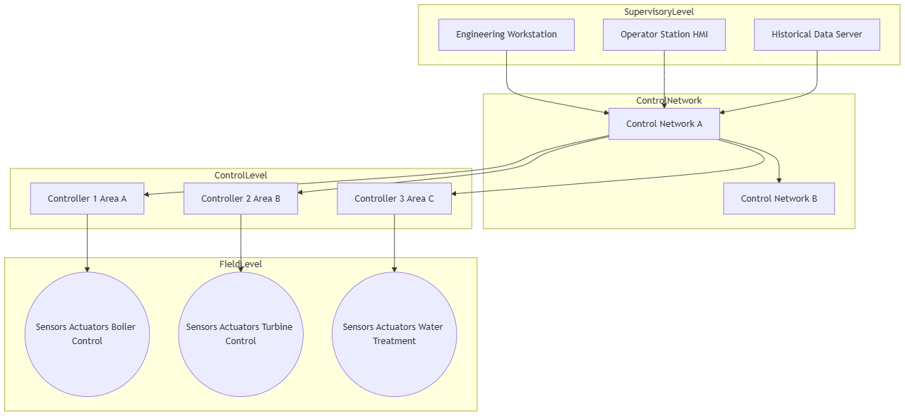
DCS Architecture Diagram
The following diagram illustrates the hierarchical and distributed nature of a typical DCS.
Advantages and Disadvantages
- Advantages: High reliability and availability due to redundancy; excellent scalability for large plants; integrated platform for control, HMI, and data historisation; powerful tools for advanced process control.
- Disadvantages: High initial investment cost; often proprietary, leading to vendor lock-in; can be slower in response time for high-speed discrete logic compared to a PLC.
Typical Applications
DCSs are the system of choice for continuous or large batch processing industries, including:
- Oil and Gas Refineries
- Chemical and Petrochemical Plants
- Power Generation Stations (Fossil Fuel, Nuclear)
- Pharmaceutical Manufacturing
- Pulp and Paper Mills
Programmable Logic Controllers (PLC)
The Programmable Logic Controller, or PLC, was born out of the American automotive industry in the late 1960s as a replacement for cumbersome and inflexible electro-mechanical relay panels. A PLC is, at its heart, a ruggedised industrial computer designed for high-speed, logic-based control of individual machines or small processes.
If a DCS is the orchestra conductor, a PLC is the highly efficient factory floor manager for a specific production cell. Its strength lies in executing sequential, discrete (on/off) logic very quickly and reliably. It operates by continuously scanning a user-created program, reading the state of inputs, executing the program logic based on these inputs, and then updating the state of outputs.
Core Components and Architecture
PLCs come in various sizes, but their core architecture remains consistent:
- Central Processing Unit (CPU): The brain that interprets the input signals, executes the control program from memory, and sends commands to the output devices.
- Memory (RAM/ROM): Stores the user program (e.g., Ladder Logic), I/O status, and other operational data.
- Input/Output (I/O) System: Comprises input modules that receive signals from devices like pushbuttons, sensors, and switches, and output modules that send signals to control devices like motors, solenoids, and indicator lights.
- Power Supply: Converts mains AC voltage into the low-voltage DC required by the PLC’s internal components.
- Programming Device: A standard laptop or dedicated programmer running specialised software to write, download, and monitor the PLC program.
PLC Architecture Diagram
The diagram below shows the fundamental scan-based operation of a PLC, processing inputs and controlling outputs.
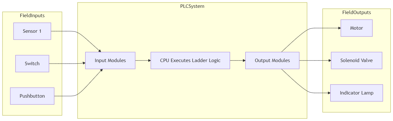
The most common language for programming PLCs is Ladder Logic (LD), which was designed to be easily understood by electricians already familiar with relay schematic diagrams. However, modern PLCs support other languages defined by the IEC 61131-3 standard, such as Function Block Diagram (FBD) and Structured Text (ST).
Advantages and Disadvantages
- Advantages: Cost-effective for smaller applications; extremely fast scan times for discrete control; robust and reliable in harsh industrial environments; flexible and easy to program for logic-based tasks.
- Disadvantages: Limited in managing complex, continuous processes compared to a DCS; integrating HMI, alarm management, and historian functions can require more effort and third-party software.
Typical Applications
PLCs are ubiquitous in discrete manufacturing and standalone machine control:
- Automotive Assembly Lines
- Food and Beverage Packaging and Bottling
- Conveyor and Material Handling Systems
- Building Automation (HVAC Control)
- Automated Test Equipment
SCADA Systems (Supervisory Control and Data Acquisition)
A SCADA system provides high-level supervision over processes that are distributed across a vast geographical area. The key terms are “Supervisory Control” and “Data Acquisition.” Unlike a DCS or PLC that provides direct, real-time control, a SCADA system’s primary role is to monitor and gather data from remote sites and issue broad commands from a central location.
Think of an air traffic control system. Controllers at a central airport don’t fly the planes directly, but they monitor their positions, altitudes, and speeds, and issue commands (e.g., “change altitude,” “turn to heading…”) to the pilots (the local controllers) to ensure the entire airspace operates safely and efficiently. SCADA is the industrial equivalent for pipelines, power grids, or water networks.
Core Components and Architecture
SCADA architecture is defined by its geographical spread:
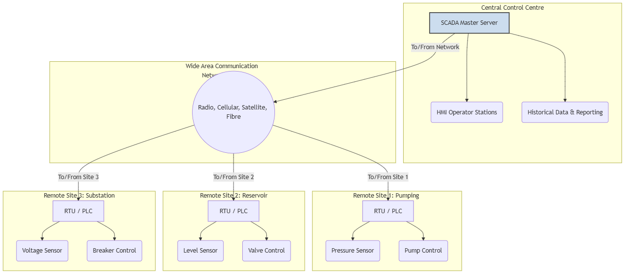
- Master Terminal Unit (MTU) / SCADA Server: The central host computer(s) that run the SCADA software. It communicates with remote field devices, processes the collected data, and displays it on the HMI.
- Remote Terminal Units (RTU) / PLCs: These are the “eyes and ears” at the remote sites. An RTU is a microprocessor-controlled device that interfaces with local sensors and actuators. It collects data, stores it, and transmits it back to the master server when polled. PLCs are increasingly used in this role due to their flexibility and power.
- Human-Machine Interface (HMI): The software that presents the process data to a human operator. It displays graphical mimics of the remote sites, logs alarms, and allows the operator to issue supervisory commands.
- Communication Infrastructure: Often the most complex part of a SCADA system. It can involve a mix of communication mediums, including radio, cellular networks, satellite, fibre optics, or public telephone lines, to connect the central server to the remote sites.
SCADA Architecture Diagram
This diagram illustrates the classic SCADA model of a central master station communicating with multiple remote field sites.
SCADA vs. DCS
While both are large-scale systems, their philosophies differ. A DCS is process-oriented, providing tight, real-time control within a contained plant. A SCADA system is data-acquisition-oriented, providing supervisory control over a geographically dispersed area where real-time feedback might be subject to communication delays.
Advantages and Disadvantages
- Advantages: Enables monitoring and control over vast areas; provides centralised data for analysis and optimisation; improves operational efficiency and response to incidents in remote locations.
- Disadvantages: System performance is highly dependent on the reliability and latency of the communication network; cybersecurity is a major concern for critical infrastructure; system integration can be complex.
Typical Applications
SCADA is essential for managing geographically distributed infrastructure:
- Electrical Power Grids (Transmission and Distribution)
- Water and Wastewater Management Systems
- Oil and Gas Pipelines and Production Fields
- Railway and Transit Systems
- Environmental Monitoring Networks
Instrumentation and Control Loop Diagrams
Regardless of whether the underlying architecture is a DCS, PLC, or SCADA system, engineers and technicians need a universal language to describe how instruments are connected and how control is achieved. This language is the Instrumentation and Control Loop Diagram, often represented in a P&ID (Piping and Instrumentation Diagram).
These diagrams are the essential blueprints for any automated process. They use standardised symbols and conventions (like ISA-S5.1) to schematically show all the equipment, piping, and instrumentation, and how they interact within a control loop.
The Anatomy of a Feedback Control Loop
A simple feedback control loop is the fundamental building block of automation. It consists of four key stages:
- Measure: A sensor measures a physical property of the process (e.g., temperature, pressure, flow, level). This is the Process Variable (PV).
- Compare: A controller compares the measured PV to the desired value, known as the Setpoint (SP).
- Compute: Based on the difference (error) between the PV and SP, the controller’s algorithm calculates a corrective action.
- Correct: The controller sends an output signal to a final control element (e.g., a control valve or a variable speed motor) to manipulate the process and bring the PV back to the setpoint.
Example: A Simple Heat Exchanger Control Loop Diagram
Let’s visualise this loop using a diagram to control the temperature of a product leaving a heat exchanger by adjusting the flow of steam.
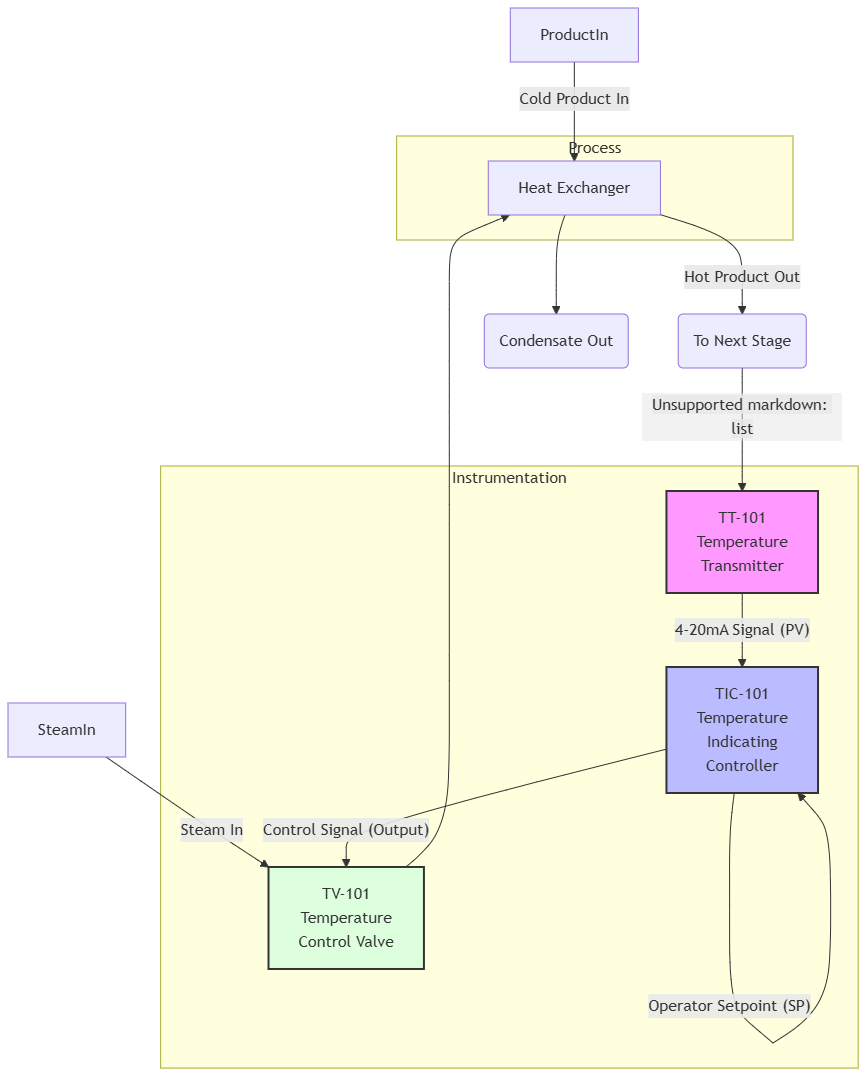
Decoding the Diagram:
- TT-101 (Temperature Transmitter): This is the sensor. It measures the temperature of the hot product and transmits it as an electrical signal (commonly 4-20mA).
- TIC-101 (Temperature Indicating Controller): This is the brain, likely a function block within a DCS or a PLC. It receives the temperature signal (PV), compares it to the operator’s setpoint (SP), and calculates an output. The “I” for “Indicating” means the operator can see the value on an HMI.
- TV-101 (Temperature Valve): This is the final control element. It’s a control valve that receives the signal from the TIC and modulates the flow of steam into the heat exchanger. If the product is too cold, the TIC will command the TV to open further, admitting more steam.
This standardised representation is critical. It allows a maintenance technician to quickly understand how the loop works, isolate faults, and perform calibrations, ensuring the process remains safe and efficient.
Conclusion: An Integrated Landscape
The worlds of DCS, PLC, and SCADA are not mutually exclusive. Modern industrial facilities are often a hybrid, leveraging the strengths of each architecture. A large refinery (a classic DCS application) will use dozens of PLCs for controlling standalone package units like compressors and boilers. This entire facility might then be monitored remotely via a corporate-level SCADA system.
The lines are blurring as technology evolves. Modern PLCs (often called PACs – Programmable Automation Controllers) have powerful process control capabilities, while modern DCSs have improved their speed for discrete logic. The rise of the Industrial Internet of Things (IIoT) and cloud computing further integrates these systems, enabling unprecedented levels of data analysis and predictive maintenance.
However, the fundamental principles remain. Understanding the process-centric nature of a DCS, the logic-centric speed of a PLC, the geographically-oriented view of SCADA, and the universal language of control diagrams provides a timeless and essential foundation for navigating the complex and fascinating world of instrumentation and control.
Discover more from Tamfis Nigeria Limited
Subscribe to get the latest posts sent to your email.