
 Hot Deals
 Shopfinish
 Shop
Shop Appliances
 Babies & Kids
 Best Selling
 Books
Books Consumer Electronics
 Furniture
 Home & Kitchen
 Jewelry
 Luxury & Beauty
 Shoes
Shoes Training & Certifications
 Wears & Clothings


Testing, Inspection, and Maintenance: Ensuring the Lifespan of Electrical Systems
In the world of electricity, installation is only half the story. The long-term reliability, efficiency, and most critically, the safety of any electrical system—be it in a home, office, or vast industrial plant—hinges on rigorous testing, inspection, and maintenance. This proactive approach not only prevents costly breakdowns and extends the lifespan of equipment but also safeguards lives from potential electrical hazards.
This section delves into the vital practices that electrical professionals undertake to ensure systems remain in peak condition. From fundamental insulation resistance checks to advanced thermal imaging, and from routine maintenance schedules to critical fault-finding techniques, we’ll explore the essential procedures that guarantee the continuous, safe, and optimal performance of electrical installations.
Diagnosing Insulation Health: Insulation Resistance Testing (Megger Use)

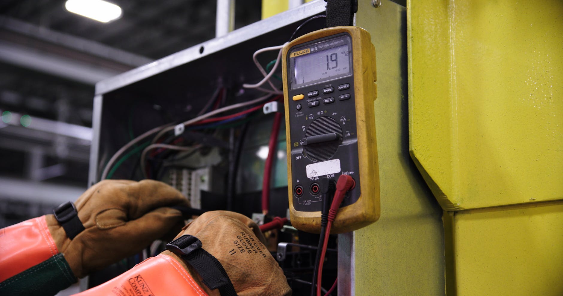
One of the most fundamental and critical tests for assessing the health of an electrical system is Insulation Resistance Testing, often performed using a device colloquially known as a Megger (a brand name for an insulation resistance tester). Over time, due to factors like heat, moisture, chemical exposure, mechanical stress, and age, the insulating materials around electrical conductors can degrade. This degradation compromises their ability to contain current, leading to leakage currents, increased losses, and eventually, insulation breakdown, which can cause short circuits, equipment damage, or electric shock.
The Principle: An insulation resistance tester applies a high DC voltage (typically 500V, 1000V, 2500V, or 5000V, depending on the system voltage) across an insulator (e.g., between a conductor and earth, or between two conductors). It then measures the tiny leakage current that flows through or over the surface of the insulation. Using Ohm’s Law (R=V/I), the device calculates the insulation resistance in megaohms (MΩ) or gigaohms (GΩ). A healthy insulation will exhibit a very high resistance.
Why it’s Crucial:
- Safety: Detects deteriorated insulation that could lead to dangerous touch voltages or electric shock.
- Preventive Maintenance: Identifies potential insulation failures before they result in catastrophic breakdowns, allowing for planned repairs.
- Equipment Lifespan: Regular testing helps to trend insulation health, enabling timely intervention to prolong the life of cables, motors, transformers, and switchgear.
- Commissioning: Verifies the integrity of new installations before energising.
- Troubleshooting: Helps pinpoint the location of an insulation fault.
Performing the Test (Simplified):
- De-energise the Circuit/Equipment: Crucially, the circuit or equipment must be completely de-energised and isolated from the power supply. Confirm with a voltage tester.
- Discharge Capacitance: If testing large cables or motors, allow time for any stored capacitive charge to dissipate, or actively discharge them using a grounding stick.
- Connect the Tester: Connect the “Line” or “Live” terminal of the Megger to the conductor being tested and the “Earth” or “Guard” terminal to the earthed metallic sheath/conduit or another conductor (for inter-conductor tests).
- Apply Test Voltage: Select the appropriate test voltage and press the test button.
- Record Readings: Observe and record the resistance reading over a specific time (e.g., 60 seconds for a spot test, or longer for a polarisation index test). Readings should generally be in the tens or hundreds of megaohms, with minimum acceptable values specified by standards (e.g., IET Wiring Regulations BS 7671 often specify 1 MΩ as a minimum for circuits operating at 500V).
Safety Warning: Insulation resistance testing involves high voltages and must only be performed by qualified and competent personnel following strict safety procedures.
Ensuring a Safe Path to Earth: Earth Testing Techniques
The earthing system is the unseen hero of electrical safety, providing a critical path for fault currents to safely dissipate into the general mass of the earth. However, an earthing system is only effective if its resistance to earth is sufficiently low. Earth testing techniques are employed to measure this resistance, ensuring the system remains compliant with safety standards and capable of fulfilling its protective role.
Why Earth Testing is Essential:
- Personnel Safety: A low earth resistance ensures that in the event of a fault, hazardous touch and step voltages are minimised, protecting individuals from electric shock.
- Equipment Protection: Limits overvoltages and prevents damage to sensitive equipment during insulation failure or lightning strikes.
- Protective Device Operation: Ensures that earth fault currents are large enough to quickly activate circuit breakers or fuses, isolating the fault.
- Compliance: Mandatory for new installations, periodic testing, and after any modifications or repairs to the earthing system, as per wiring regulations.
Common Earth Testing Techniques:
- Fall-of-Potential Method (3-Point or 4-Point Test):
- This is the most accurate and widely used method for measuring the overall resistance of a large earthing electrode or system.
- Procedure: An earth resistance tester (a specialised instrument) is connected to the earth electrode under test (EUT). Two auxiliary electrodes (Current Spike ‘C’ and Potential Spike ‘P’) are driven into the ground at specific distances away from the EUT, forming a straight line. The tester injects a known current between the EUT and the Current Spike and measures the voltage drop between the EUT and the Potential Spike. The earth resistance is then calculated (R=V/I).
- Spacing: Critical to accuracy. The Potential Spike must be placed far enough away from both the EUT and the Current Spike to be outside their respective resistance areas of influence (typically 62% of the total distance between EUT and Current Spike, or often tested with varying distances to find a plateau).
- Dead Earth Method (2-Point Test):
- A simpler, less accurate method suitable for confirming continuity to an existing, known good earth (e.g., a metallic water pipe or a known effective main earth bar).
- Procedure: One lead of the earth tester is connected to the EUT, and the other to the known good earth. The tester measures the combined resistance of both earths.
- Limitation: It cannot determine the resistance of the EUT in isolation and relies on the assumption that the reference earth is genuinely low resistance.
- Selective Testing (Clamp-On Method):
- A non-intrusive method using a clamp-on earth resistance tester, ideal for multi-earthed systems where disconnecting the earth electrode is impractical.
- Procedure: The clamp is placed around the earth conductor. The tester induces a voltage onto the conductor and measures the resulting current flowing to earth.
- Benefit: No need for auxiliary spikes or disconnecting the earth conductor, making it quick and convenient for routine checks in complex systems. It measures the resistance of a single earth electrode in parallel with other earths.
Safety Warning: Earth testing should only be carried out by trained professionals, as it involves working with electrical connections to the earth system.
Seeing the Unseen: Thermal Imaging for Electrical Systems
Thermal imaging (or thermography) uses infrared cameras to detect and visualise heat patterns emitted by objects. In electrical systems, this non-contact, non-destructive technique has become an invaluable diagnostic tool, as heat is often the first sign of an impending electrical problem.
The Principle: All objects with a temperature above absolute zero emit infrared radiation. The hotter an object, the more infrared radiation it emits. Thermal cameras detect this radiation and convert it into a visible image, where different colours represent different temperatures (typically hotter areas appear brighter or in warmer colours like red/yellow, while cooler areas are darker or in cooler colours like blue/green).
Why it’s Crucial for Electrical Systems:
- Early Fault Detection: Identifies abnormal hot spots in electrical components before they lead to failure, fire, or costly downtime.
- Predictive Maintenance: Enables condition monitoring, allowing engineers to trend temperature changes and schedule repairs proactively during planned outages, rather than reacting to catastrophic failures.
- Safety: Pinpoints dangerous overheating, preventing potential fires or equipment explosions (e.g., arc flashes).
- Non-Intrusive: Can be performed on live equipment without shutting down the system, minimising disruption.
- Identification of Issues: Reveals problems such as:
- Loose Connections: High resistance at loose terminals or splices generates heat.
- Overloaded Circuits: Conductors or components carrying excessive current will overheat.
- Unbalanced Loads: Uneven current distribution in three-phase systems can lead to overheating on one phase.
- Failing Components: Deteriorating contacts in breakers or switches, faulty transformers, or stressed motor windings can generate excess heat.
- Insulation Degradation: Hot spots can indicate stressed or damaged insulation.
Typical Applications:
- Switchgear and Distribution Boards: Inspecting circuit breakers, fuses, busbar connections, and contactors.
- Transformers: Checking bushings, cooling fins, and winding temperatures.
- Motors: Detecting overheating bearings or windings.
- Cables and Conductors: Identifying overloaded cables or problematic cable joints.
- Control Panels: Locating hot relays, terminals, or power supplies.
A trained thermographer can interpret the thermal images and understand the significance of temperature differences, making thermal imaging an indispensable part of a comprehensive electrical maintenance programme.
Staying Ahead of the Curve: Routine Electrical Maintenance Checklist
Proactive maintenance is far more cost-effective and safer than reactive repairs. A comprehensive routine electrical maintenance checklist is essential for ensuring the ongoing reliability, efficiency, and safety of any electrical installation. This checklist should be tailored to the specific environment (residential, commercial, industrial) and the age/complexity of the system.
General Categories for a Maintenance Checklist:
- Visual Inspection:
- Check for signs of overheating (discolouration, melting insulation), arcing (soot marks), or water ingress.
- Inspect cables and conduits for damage, fraying, or exposed conductors.
- Verify all cover plates, panel doors, and enclosures are securely fastened and intact.
- Check for proper labelling and identification of circuits and equipment.
- Ensure adequate ventilation for electrical enclosures and rooms.
- Look for dust, dirt, or debris buildup that could impede cooling or cause tracking.
- Check for pest infestations that might damage wiring.
- Tightness of Connections:
- Loose connections are a primary cause of overheating, arcing, and failures.
- Use a torque wrench where specified to ensure terminal screws and busbar connections are tightened to the manufacturer’s recommendations. This applies to circuit breakers, contactors, relays, busbar joints, and terminal blocks.
- Cleaning:
- De-energise and clean electrical panels, motor control centres (MCCs), and switchgear to remove dust, dirt, and moisture. Compressed air (non-conductive) or vacuum cleaners are often used.
- Clean insulators on busbars and outdoor equipment.
- Operational Checks:
- Circuit Breakers: Manually trip and reset breakers to ensure their mechanical operation (if safe to do so and within recommended test intervals). Check for proper operation of earth leakage/residual current devices (RCDs) by pressing their test buttons.
- Contactors and Relays: Check for free movement of contacts and absence of excessive pitting or burning.
- Motors: Listen for abnormal noises, check vibration levels, monitor bearing temperatures (if possible), and ensure proper ventilation.
- Lighting: Replace faulty lamps, check ballasts, and clean luminaires.
- Testing (as per regulatory requirements and trending):
- Insulation Resistance Tests (Meggering).
- Earth Resistance Tests.
- Thermal Imaging (as discussed).
- Voltage and Current Measurements (to check for overloads or imbalances).
- Functionality tests for safety devices (e.g., emergency stops).
- Documentation:
- Maintain accurate records of all maintenance activities, including dates, findings, actions taken, and readings. This data is invaluable for trending equipment health and scheduling future maintenance.
Frequency: The frequency of maintenance varies based on the type of installation, environment, usage, and criticality of equipment. This could range from daily operational checks in critical industrial settings to annual or biennial professional inspections for residential properties. Adhering to manufacturer recommendations and local wiring regulations (e.g., BS 7671 in the UK/Nigeria) is paramount.
Appliance Safety: PAT Testing (Portable Appliance Testing)
Portable Appliance Testing (PAT Testing) is a routine process of visually inspecting and electrically testing portable electrical appliances to ensure they are safe to use. While the term “portable appliance” is used, PAT testing generally applies to all electrical equipment that has a plug and can be connected to the mains electricity supply, regardless of its actual portability. This includes everything from kettles and desktop computers to power tools and extension leads.
Why PAT Testing is Important (especially in workplaces):
- Legal Compliance: In many jurisdictions (including the UK, where it’s widely practiced and enshrined in the Electricity at Work Regulations 1989), employers have a legal duty to ensure electrical equipment is safe and properly maintained. While PAT testing isn’t explicitly mandated, it’s a common and effective way to demonstrate compliance.
- User Safety: Prevents electric shocks, burns, and fires caused by faulty appliances, protecting employees, customers, and tenants.
- Insurance Requirements: Many insurance policies require regular electrical safety checks, including PAT testing, for businesses and landlords.
- Preventive Maintenance: Identifies potential faults before they become dangerous or cause equipment failure.
The PAT Testing Process:
- Visual Inspection (80-90% of faults found here):
- Check the plug for damage, correct fuse rating, and proper wiring.
- Inspect the cable for cuts, abrasions, fraying, or signs of overheating.
- Examine the appliance casing for damage, loose parts, or ventilation obstructions.
- Check for signs of discolouration or burning near inlets/outlets.
- Verify that cord grips are secure.
- Electrical Tests (using a PAT Tester):
- Earth Continuity Test: For Class I appliances (those with a metal casing and an earth wire), this test verifies that the earth conductor provides a continuous low-resistance path from the plug’s earth pin to the appliance’s metal casing. This is crucial for shock protection.
- Insulation Resistance Test: Checks the integrity of the insulation between the current-carrying conductors and the earth (or between live and neutral for Class II appliances).
- Leakage Current Test (or Protective Conductor Current): Measures any current leaking from the appliance’s live parts to its earthed casing or to the user.
- Polarity Test (for Extension Leads): Checks that the live, neutral, and earth conductors are wired correctly in multi-socket extensions.
- Labelling and Record Keeping:
- Each passed appliance is typically labelled with a “Pass” sticker, date of test, and next test due date.
- Detailed records are kept for all tested appliances, including results, failures, and remedial actions.
Frequency: The frequency of PAT testing varies based on the type of appliance, its usage environment (e.g., construction site vs. office), and the risk assessment. High-risk equipment in harsh environments might be tested quarterly, while office equipment might be tested annually or less frequently.
PAT testing is a relatively simple yet highly effective safety measure that plays a vital role in maintaining electrical safety in workplaces and rented properties.
Maintaining Precision: How to Calibrate Electrical Measuring Instruments
Accurate electrical measurements are the foundation of effective electrical engineering and safety. However, over time, all measuring instruments can drift out of specification due to wear, environmental factors, or damage. Calibrating electrical measuring instruments is the process of comparing the readings of a test instrument against a known, highly accurate reference standard to ensure its precision and accuracy.
Why Calibration is Crucial:
- Accuracy and Reliability: Ensures that instruments provide correct and trustworthy measurements, which is critical for design, troubleshooting, and safety. Incorrect measurements can lead to faulty designs, misdiagnosed problems, and unsafe conditions.
- Compliance and Standards: Many industries and regulations (e.g., ISO 9001 quality management systems, specific electrical standards) mandate regular calibration of testing equipment.
- Legal and Contractual Requirements: In many professional fields, having calibrated instruments is a legal or contractual requirement.
- Cost Savings: Prevents costly rework, material waste, and equipment damage that can result from inaccurate measurements.
- Traceability: Calibration establishes a clear chain of comparison back to national or international measurement standards, providing confidence in the results.
The Calibration Process (General Steps):
- Reference Standards: Calibration is performed using highly accurate reference instruments (calibrators) whose accuracy is traceable to a national metrology institute (e.g., NPL in the UK, NIST in the USA, or equivalent bodies in Nigeria).
- Comparison: The instrument under test (e.g., a multimeter) is connected in series or parallel with the reference standard, and both measure the same known input (e.g., a precise voltage, current, or resistance from the calibrator).
- Measurement and Adjustment: The readings from the test instrument are compared to the reference standard. If a deviation exceeds the acceptable tolerance, adjustments are made to the test instrument’s internal settings to bring it back within specification.
- Before and After Readings: Records are kept of both “as found” (before adjustment) and “as left” (after adjustment) readings.
- Calibration Certificate: A formal certificate is issued, detailing the instrument’s identification, calibration date, next due date, the standards used, and the results.
Frequency of Calibration: The frequency depends on several factors:
- Manufacturer’s Recommendation: Always a good starting point.
- Usage Frequency: More frequently used instruments may require more frequent calibration.
- Application Criticality: Instruments used in critical safety or high-precision applications are calibrated more often.
- Environmental Conditions: Instruments used in harsh environments may need more frequent checks.
- Past Performance: Trending calibration results can help determine optimal intervals.
Calibration is not merely a formality; it’s a vital quality control process that underpins the accuracy and reliability of all electrical work, ultimately contributing to safety and efficiency.
The Detective Work: Electrical Fault Finding Techniques
When an electrical system malfunctions, it’s akin to a detective story where the fault is the culprit. Electrical fault finding techniques are the methodical processes employed by electricians and engineers to diagnose and locate the cause of an electrical problem. Effective fault finding requires a combination of systematic thinking, knowledge of electrical principles, and proper use of testing equipment.
Common Types of Electrical Faults:
- Open Circuit: A break in the circuit, preventing current flow (e.g., a broken wire, tripped breaker, faulty switch).
- Short Circuit: An unintended low-resistance path between live conductors or between a live conductor and earth, leading to dangerously high current flow and often tripping protective devices.
- Earth Fault (Ground Fault): A specific type of short circuit where a live conductor makes unintentional contact with an earthed metallic part or the earth itself.
- Overload: Too much current drawn from a circuit, exceeding its design capacity.
- Intermittent Fault: A fault that appears and disappears sporadically, making it particularly challenging to diagnose.
Systematic Fault Finding Approach:
- Gather Information (Observe & Question):
- What are the symptoms? (e.g., no power, flickering lights, burning smell, tripped breaker).
- When did it occur? (e.g., after rain, after plugging in an appliance).
- What changed? (e.g., recent repair, new appliance).
- Are other circuits affected?
- Safety First:
- Always isolate and de-energise the circuit before performing any physical checks or resistance tests. Verify with a voltage tester.
- Wear appropriate Personal Protective Equipment (PPE).
- Visual Inspection:
- Check the most obvious culprits first: tripped circuit breakers, blown fuses, loose connections at outlets/switches, visible damage to cables or appliances, scorch marks.
- Divide and Conquer (Sectionalise the Circuit):
- Mentally or physically break down the circuit into smaller, manageable sections.
- For example, if an entire branch circuit is dead, start at the breaker panel. If only one outlet is dead, focus on that outlet and its immediate wiring.
- Use Test Instruments Systematically:
- Multimeter:
- Voltage Test: Check for voltage at the supply point to the circuit and progressively further down the circuit to identify where power is lost.
- Continuity Test: With power off, check for continuity across wires, switches, and components to find open circuits.
- Resistance Test: With power off, measure resistance of components (e.g., motor windings, heating elements) to check for open circuits or abnormally low resistance (short circuits).
- Insulation Resistance Tester (Megger): To check for insulation breakdown (earth faults or short circuits between conductors).
- Clamp Meter: To measure actual current draw on a live circuit (safely!) to check for overloads or unbalanced currents.
- Multimeter:
- Verify and Test:
- Once a potential fault is identified (e.g., a loose wire, a faulty component), correct it.
- Before re-energising, perform final safety checks (e.g., insulation resistance test on the repaired section).
- Restore power and test the circuit thoroughly to confirm the fault is resolved and no new issues have been introduced.
- Document: Record the fault, its cause, and the repair action for future reference.
Effective fault finding minimises downtime, prevents further damage, and ensures the rapid restoration of safe electrical operation.
The Grand Finale: Testing and Commissioning of Electrical Installations
Once an electrical installation, whether a simple residential upgrade or a complex industrial plant, is complete, it’s not simply switched on. A rigorous process of testing and commissioning is undertaken to ensure that the system is installed correctly, operates safely, performs as designed, and complies with all relevant standards and regulations.
Testing: This phase involves a series of prescribed electrical tests performed on individual components and entire circuits. These are typically carried out by qualified electricians or commissioning engineers.
Key Tests (often mandated by wiring regulations like BS 7671):
- Continuity of Protective Conductors: Verifies that all earth conductors and bonding conductors provide a continuous, low-resistance path to the main earthing terminal.
- Continuity of Ring Final Circuit Conductors (if applicable): Checks the integrity of ring circuits (common in UK residential wiring).
- Insulation Resistance Tests: As discussed previously, to confirm the integrity of insulation between live conductors and earth, and between live conductors themselves.
- Polarity Tests: Ensures that connections are correctly phased (live, neutral, earth) throughout the installation.
- Earth Electrode Resistance Test: Measures the resistance of the main earthing electrode to the general mass of earth.
- Earth Fault Loop Impedance (EFLI) Test: Measures the impedance of the earth fault loop, which is critical for ensuring that protective devices (breakers/fuses) operate quickly enough during an earth fault to disconnect the supply and prevent dangerous shocks.
- RCD (Residual Current Device) Testing: Verifies that RCDs trip within the specified time and at the correct fault current.
- Functional Tests: Confirming that all switches, outlets, lights, control systems, motors, and other equipment operate as intended.
Commissioning: This phase involves energising the system (or parts of it) and verifying its overall performance in real-world conditions. It’s a more holistic process than just testing individual components.
Key Aspects of Commissioning:
- Energisation: Safely bringing the system online, often in a phased manner.
- System Integration: Ensuring that all sub-systems (e.g., power distribution, control systems, lighting, HVAC, safety interlocks) work together seamlessly.
- Performance Verification: Measuring parameters like voltage levels, current draws, power factor, and comparing them against design specifications.
- Protective Device Coordination Checks: Verifying that protective relays and circuit breakers operate in the correct sequence and within their settings during simulated faults.
- Functional Performance Tests: Running equipment through its full operating range, checking sequences, interlocking, and alarm functionalities.
- Training: Training for operational and maintenance staff on the new system.
- Documentation Handover: Providing comprehensive “as-built” drawings, manuals, test reports, and maintenance schedules to the client.
The testing and commissioning process is a final quality assurance step, ensuring that the new electrical installation is safe, reliable, efficient, and ready for operation. It requires meticulous planning, skilled personnel, and adherence to all relevant standards.
The Golden Rule of Safety: Lockout/Tagout (LOTO) Procedures
Lockout/Tagout (LOTO) procedures are paramount safety protocols used in industrial and commercial settings to prevent accidental energisation or start-up of machinery or electrical circuits during maintenance, repair, or service activities. The principle is simple: if you’re working on it, you must ensure it cannot be energised.
The Danger: Without LOTO, unexpected start-up of machinery or release of hazardous energy (electrical, mechanical, hydraulic, pneumatic, thermal, chemical) can cause severe injury or even death to workers.
The LOTO Procedure:
- Preparation:
- Identify all energy sources for the equipment (electrical, pneumatic, hydraulic, etc.).
- Notify all affected personnel that the equipment will be de-energised.
- Shutdown:
- De-energise the equipment following established shutdown procedures.
- Isolation:
- Physically isolate the equipment from all energy sources. For electrical systems, this means turning off the circuit breaker, pulling fuses, or opening a disconnect switch.
- Crucially, verify the absence of voltage using a suitable voltage tester at the point of work. This step cannot be skipped.
- Lockout:
- Apply a lockout device (e.g., a padlock) to the energy-isolating device (e.g., the circuit breaker handle, disconnect switch). Each worker working on the equipment applies their own personal lock. This ensures that no one else can re-energise the equipment while they are working.
- Lockout devices must be durable, unique, and clearly identify the person who applied them.
- Tagout:
- Attach a tagout device (a prominent warning tag) to the lockout device. The tag typically states “DO NOT OPERATE,” “DANGER,” and provides information about why the equipment is locked out, who applied the lock, and when.
- Stored Energy Release:
- Safely release or neutralise any stored residual energy (e.g., discharge capacitors, block moving parts, relieve hydraulic pressure).
- Verification:
- Attempt to start the equipment (e.g., by pressing the start button) to confirm that it is truly de-energised and cannot be started. Return controls to “OFF” position after verification.
- Perform Work:
- Only now is it safe to begin maintenance or repair work.
- Restoration:
- When work is complete, verify tools and personnel are clear, notify affected personnel, remove locks/tags (only by the person who applied them), and re-energise the equipment following established procedures.
LOTO is a non-negotiable safety procedure. Strict adherence to LOTO protocols is a cornerstone of workplace electrical safety, preventing thousands of injuries and fatalities each year.
The Health Monitor: Condition Monitoring of Electrical Equipment
Beyond scheduled routine maintenance, condition monitoring is a proactive strategy that involves continuously or periodically collecting data on the performance and health of electrical equipment to detect early signs of degradation or impending failure. This allows for planned, condition-based maintenance (CBM) rather than fixed-interval or reactive maintenance, leading to significant cost savings, reduced downtime, and improved reliability.
Key Condition Monitoring Techniques for Electrical Equipment:
- Vibration Analysis:
- What it detects: Imbalance, misalignment, bearing wear, looseness in rotating machinery (motors, generators, pumps).
- How it works: Sensors measure the amplitude and frequency of vibrations. Changes in vibration patterns indicate developing faults.
- Oil Analysis (for Transformers, Oil-filled Switchgear):
- What it detects: Degradation of insulating oil due to heat, moisture, or chemical contamination. Also, dissolved gases in oil can indicate internal arcing or overheating of windings/insulation.
- How it works: Regular laboratory testing of oil samples for dielectric strength, acidity, moisture content, dissolved gas analysis (DGA), and particulate count.
- Thermal Imaging (Infrared Thermography):
- What it detects: Hot spots indicating loose connections, overloaded circuits, failing components, unbalanced loads, or insulation degradation.
- How it works: As discussed previously, infrared cameras visualise heat patterns.
- Partial Discharge (PD) Testing:
- What it detects: Small electrical discharges that occur within the insulation of high-voltage equipment (cables, switchgear, transformers) before complete insulation breakdown. PD is a precursor to major insulation failure.
- How it works: Specialised instruments detect acoustic, electromagnetic, or chemical signals associated with PD.
- Motor Current Signature Analysis (MCSA):
- What it detects: Faults in electric motors such as broken rotor bars, stator winding issues, bearing defects, or air gap eccentricities.
- How it works: Analyses the frequency spectrum of the motor’s operating current to identify characteristic fault signatures.
- Ultrasonic Testing:
- What it detects: Arcing, tracking, corona discharge, and internal faults in switchgear and other electrical enclosures that generate ultrasonic noise. Also used to detect bearing friction in rotating equipment.
- How it works: Uses ultrasonic detectors to pick up sounds above the human hearing range.
- Battery Monitoring Systems (for UPS, DC systems):
- What it detects: Battery cell voltage imbalances, internal resistance changes, temperature anomalies, and overall state of health, predicting battery end-of-life.
Benefits of Condition Monitoring:
- Reduced Downtime: Allows for planned maintenance before catastrophic failure.
- Cost Savings: Avoids expensive emergency repairs and prevents secondary damage.
- Extended Asset Life: Addressing issues early prolongs equipment lifespan.
- Improved Safety: Reduces the risk of electrical hazards by identifying deteriorating conditions.
- Optimised Maintenance Scheduling: Moves from time-based to condition-based maintenance, performing work only when needed.
Condition monitoring, often integrated with advanced data analytics and AI, is transforming electrical maintenance from a reactive necessity into a strategic element of operational excellence.
Discover more from Tamfis Nigeria Limited
Subscribe to get the latest posts sent to your email.